36
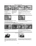
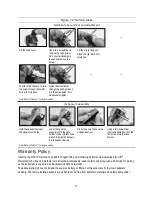
Figure 7.2 Service tasks
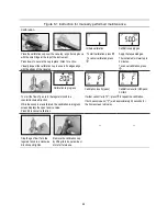
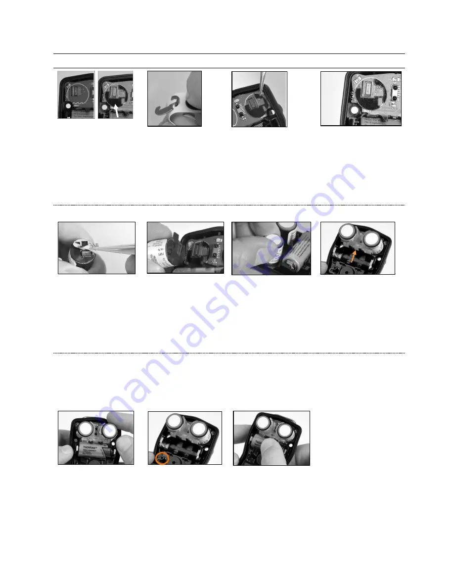
Check the circuit board for a
black polycarbonate plate in
each sensor position.
The plate is absent in the left
image. The right image
shows the plate. If both plates
are present, skip to sensor
placement below.
The plates are affixed to a paper backing. Bend the paper
backing to separate the plate.
Lightly grip the plate near its top with tweezers; gently lift to
completely remove from paper backing.
Guide the plate
—
adhesive side down
—
for correct placement
on the circuit board as shown above (right).
Using a clean, soft cloth,
press gently into place.
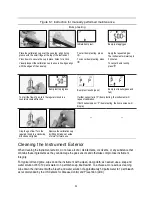
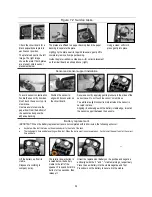
Sensor and sensor support installation
To avoid sensor contamination,
handle the sensor by its sides.
Don’t touch the
sensor top, its
membrane.
Use tweezers to remove the
paper liner from the bottom of
the sensor and expose the
adhesive backing.
Position the sensor to
align with its connector on
the circuit board.
Secure sensor by applying gentle pressure to the sides of the
sensor case.
Do not touch the sensor's membrane
.
You will feel a slight connection impact when the sensor is
secured in place.
Aligning its wider edge with the battery-cradle edge, reinstall
the sensor support between the sensors.
Battery replacement
IMPORTANT:
When the battery replacement task is
not
completed within 60 minutes, the following will occur:
•
Any data will be lost that was not downloaded prior to the start of the task.
•
The instrument’s time and date settings will be lost. When the
instrument is next powered on, it will prompt the user to enter the correct
time and date.
—
Lift the battery up from its
cradle.
Dispose of according to
company policy.
The interior power button is
located below the battery
cradle to the left of the
speaker. Press and hold this
button for two seconds, then
release it.
Orient the replacement battery so the positive and negative
ends align with the "+" and "
−
" cradle markings, respectively.
Place the new battery into the cradle negative end first.
Press down on the battery to secure it in the cradle.
Summary of Contents for TANGO TX2
Page 6: ......
Page 16: ......
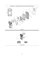
Page 38: ...32 Illustration 7 1 Disassembled Tango TX2 and case top assembly Instrument Case top assembly...

