background image

Ref. IS.MDUINO.XXX 


Summary of Contents for M-DUINO PLUS series

Page 1: ...Ref IS MDUINO XXX M DUINO PLUS FAMILY M Duino PLUS Family User Guide ...

Page 2: ...Ref IS MDUINO XXX ...

Page 3: ...Ref IS MDUINO XXX Ethernet PLC User Guide Revised March 2018 ...

Page 4: ...for the following audience Persons in charge of introducing automation devices Persons who design automation systems Persons who install or connect automation devices Persons who manage working automation installation Warnings Unused pins should not be connected Ignoring the directive may damage the controller Improper use of this product may severely damage the controller Refer to the controller ...

Page 5: ...es regulations or standards that apply to the combination of products in the customer s application or use of the product The following are some examples of applications for which particular attention must be given This is not intended to be an exhaustive list of all possible uses of the products nor is it intended to imply that the uses may be suitable for the products Systems machines and equipm...

Page 6: ...roduct specifications and accessories may be changed at any time based on improvements and other reasons It is our practice to change model numbers when features are changed or published ratings or when significant construction changes are made However some specifications of the products may be changed without any notice When in doubt special numbers may be assigned to fix or stablish key specific...

Page 7: ...THE PRODUCTS WILL SUITABLY MEET THE REQUIREMENTS OF THEIR INTENDED USE INDUSTRIAL SHIELDS DISCLAIMS ALL OTHER WARRANTIES EXPRESS OR IMPLIED Limitations of Liability INDUSTRIAL SHIELDS SHALL NOT BE RESPONSIBLE FOR SPECIAL INDIRECT OR CONSEQUENTIAL DAMAGES LOSS OF PROFITS OR COMERCIAL LOSS IN ANY WAY CONNECTED WITH THE PRODUCTS WHETHER SUCH CLAIM IS BASED ON CONTRACT WARRANTY NEGLIGENCE OR STRICT LI...

Page 8: ...tions 16 3 1 Arduino Board 16 3 2 Intended Audience 16 3 3 General Precautions 16 Software interface 16 How to connect PLC Arduino to PC 19 How to connect PLC to power supply 20 M duino Family Pinout 21 7 1 A Zone connection 21 7 2 B Zone 23 7 2 1 Analog Shield 23 7 2 2 Relay Shield 24 7 3 C Zone 25 7 3 1 Analog Shield C Zone 25 7 3 2 Relay Shield C Zone 26 7 4 D Zone 27 7 4 1 Analog Shield D Zone...

Page 9: ... 9 3 Serial 1 RX1 TX1 33 9 4 SPI MISO MOSI SCK 33 9 5 Pin 2 Pin 3 34 A Zone Features Communications RTC uSD 34 10 1 RS 232 34 10 2 RS 485 34 10 3 I2C 35 10 4 SPI 35 10 5 TTL 36 10 6 Ethernet 36 10 7 RTC 36 10 8 uSD 37 I O technical details 38 Typical Connections 40 40 Connector details 44 Mechanical Characteristics 45 ...

Page 10: ... X and relays as R0 X The inputs in the zone C are named I1 X being X any number suitable in the Shield Outputs are named as Q1 X and relays as R1 X The inputs in the zone D are named I2 X being X any number suitable in the Shield Outputs are named as Q2 X and relays as R2 X 1 2 Zone Distribution A zone is completely common for every single M Duino Family PLC The rest of zones can have two differe...

Page 11: ...ork as Analog Output 11 Inputs 11 Digital Inputs 4 of which can work as Analog Input 6 Outputs 6 Digital Outputs 2 of which can work as Analog Outputs Relay Shield 6 Inputs 6 Digital Inputs 4 of which can work as Analog Input 11 Outputs 8 Relay Outputs 3 Digital Outputs 3 of which can work as Analog Output 6 Inputs 6 Digital Inputs 4 of which can work as Analog Input 11 Outputs 8 Relay Outputs 3 D...

Page 12: ...a Zones B C D which are Analog Relay Relay respectively It has 53 I Os M Duino B Zone C Zone D Zone M Duino53ARR A R R There are 2 different exceptions M Duino38R M Duino57R should be called with this nomenclature M Duino38RR M Duino57RRR as everything is Relay it is omitted Also for the M duino21 42 58 as they are all Analog they are not represented with this nomenclature With the nomenclature re...

Page 13: ...Ref IS MDUINO XXX 1 4 Mechanical dimension M Duino 1 BLOCK I Os M Duino 2 BLOCKS I Os M Duino 3 BLOCKS I Os ...

Page 14: ... Dig Input 10bit 0 10Vcc 0 to 10V Input Impedance 39K Separated PCB ground Digital Isolated Input 24Vcc 7 to 24Vdc I min 2 to 12 mA Galvanic Isolation Interrupt isolated Input HS 24Vcc 7 to 24Vdc I min 2 to 12 mA Galvanic Isolation Analog Output 8bit 0 10Vcc 0 to 10Vdc I max 20 mA Separated PCB ground Digital Isolated Output 24Vcc 5 to 24Vdc I max 70 mA Galvanic Isolation Diode Protected for Relay...

Page 15: ...ance 80m s2 in the X Y and Z direction 2 times each Ambient temperature operating 0º to 45ºC Ambient humidity operating 10 to 90 no condensation Ambient environment operating With no corrosive gas Ambient temperature storage 20º to 60ºC Power supply holding time 2ms min Weight 445g max 542g max 850g max 2 2 Performance Specification Arduino Board ARDUINO MEGA 2560 Control method Stored program met...

Page 16: ...d property if used improperly consult your INDUSTRIAL SHIELDS representative Ensure that the rating and performance characteristics of M Duino are sufficient for the systems machines and equipment and be sure to provide the systems machines and equipment double safety mechanisms This manual provides information for programming and operating the M Duino Software interface Industrial Shields PLC are...

Page 17: ...le Preferences located in the top left corner 2 In Additional Boards Manager URLs write the following http apps industrialshields com main arduino boards package_industrialshields_index json 3 Press OK to save the changes 4 Go to Tools Board Boards Manager ...

Page 18: ...ck install selecting the latest version Following these steps you will be able to see now the Industrial Shields Boards Once it is selected the Ardbox Family or M Duino family an extra option will appear on Tools There it can be selected the exact model for every family ...

Page 19: ...thermore there are some extra libraries that can be found in Industrial Shields github https github com IndustrialShields How to connect PLC Arduino to PC Connect USB port from PLC to PC NOTE M Duino Family uses USB B cable Open Arduino IDE interface Select Industrial Shields boards M Duino Family ...

Page 20: ... port How to connect PLC to power supply M Duino Family PLCs are 12 24Vdc supplied IMPORTANT The polarity IS NOT REVERSAL Make sure that the live and GND connector of the power supply match the PLC Make sure that the power supply mains output is not higher than 24Vdc ...

Page 21: ...Reset Vin5 PIN2 GND GND 24Vdc 21 20 1 0 19 18 16 17 3 50 51 52 Reset Vin5 2 I2C SS I2C SS RX0 SS TX0 SS RX1 SS TX1 SS RX2 serial 2 TX2 serial 2 RS485 RS485 RS485 RS485 Arduino Pin SPI SPI SPI SPI 5V Arduino Pin Gnd Gnd Power Supply Not recommended for industrial applications The Jack connector needs to be removed and use the live and GND connectors Configuration Switch see section 8 for configurin...

Page 22: ...hen uploading code to Arduino Mega set switch to ON Base common unit A Zone M Duino Connector Arduino Pin Function AREF IOREF2 IOREF1 7Vdc GND 3 3Vdc GND 5Vdc GND AREF IOREF2 IOREF1 7Vdc GND 3 3Vdc GND 5Vdc GND Arduino PIN Arduino PIN Arduino PIN GND Arduino PIN GND GND Ethernet Arduino Power Connector Reset button USB programmer Autoreset connector ...

Page 23: ...GND I0 3 Digital Input GND I0 2 Digital Input GND I0 1 Digital Input GND I0 0 Digital Input B Zone M Duino Connector Arduino Pin Function GND A0 71 A0 61 A0 51 Q Vdc COM Q0 71 Q0 61 Q0 51 Q0 4 Q0 3 Q0 2 Q0 1 Q0 0 GND 6 5 4 6 5 4 40 39 38 37 36 GND Analog Out Analog Out Analog Out External Isolated Out Vdc External Isolated Out GND Digital PWM Out Digital PWM Out Digital PWM Out Digital Out Digital...

Page 24: ... External Isolated Out Gnd External Isolated Out Vdc B Zone M Duino Connector Arduino Pin Function R0 3 R0 2 R0 1 GND I0 5 I0 4 I0 3 I0 2 I0 11 I0 1 I0 01 I0 0 25 22 23 GND 57 56 55 54 3 2 Relay Out Relay Out Relay Out GND Analog Digital Input Analog Digital Input Analog Digital Input Analog Digital Input Interrupt 1 In GND I0 1 Interrupt 0 In GND I0 0 Top Zone Led indicator I Os state Relay Outpu...

Page 25: ...put GND I1 3 Digital Input GND I1 2 Digital Input GND I1 1 Digital Input GND I1 0 Digital Input C Zone M Duino Connector Arduino Pin Function GND A1 71 A1 61 A1 51 Q Vdc COM Q1 71 Q1 61 Q1 51 Q1 4 Q1 3 Q1 2 Q1 1 Q1 0 GND 7 9 8 7 9 8 45 44 43 42 41 GND Analog Out Analog Out Analog Out External Isolated Out Vdc External Isolated Out GND Digital PWM Out Digital PWM Out Digital PWM Out Digital Out Dig...

Page 26: ...PWM Out External Isolated Out GND External Isolated Out Vdc C Zone M Duino Connector Arduino Pin Function R0 3 R0 2 R0 1 GND I0 5 I0 4 I0 3 I0 2 I0 11 I0 1 I0 01 I0 0 30 27 28 GND 63 62 61 60 19 18 Relay Out Relay Out Relay Out GND Analog Digital Input Analog Digital Input Analog Digital Input Analog Digital Input Interrupt 1 In GND I0 1 Interrupt 0 In GND I0 0 Relay Outputs Analog Output Switch C...

Page 27: ...ND I2 3 Digital Input GND I2 2 Digital Input GND I2 1 Digital Input GND I2 0 Digital Input D Zone M Duino Connector Arduino Pin Function GND A2 7 A2 61 A2 51 Q Vdc COM Q2 7 Q2 61 Q2 51 Q2 4 Q2 3 Q2 2 Q2 1 Q2 0 GND NC 13 12 NC 13 12 NC 49 48 47 53 GND Analog Out Analog Out External Isolated Out Vdc External Isolated Out GND Digital PWM Out Digital PWM Out Digital Out Digital Out Digital Out Digital...

Page 28: ... Isolated Out GND External Isolated Out Vdc D Zone M Duino Connector Arduino Pin Function R2 3 R2 2 R2 1 GND I2 5 I2 4 I2 3 I2 2 I2 11 I2 1 I2 01 I2 0 35 32 33 GND 69 68 67 66 21 20 Relay Out Relay Out Relay Out GND Analog Digital Input Analog Digital Input Analog Digital Input Analog Digital Input Interrupt 1 In GND I2 1 Interrupt 0 In GND I2 0 Relay Outputs Analog Output Switch Configuration Dig...

Page 29: ... enables SDA and disables I2 5 If it is a Relay Shield I2 5 is changed for I2 0 2 RX1 I1 6 Choosing between RX1 or the input I1 6 If this switch is ON it enables the I1 6 input and disables the RX1 If this switch is OFF it enables RX1 and disables I1 6 If it is a Relay Shield I1 6 is changed for I1 0 1 TX1 I1 5 Choosing between TX1 or the input I1 5 If this switch is ON it enables the I1 5 input a...

Page 30: ...be set always to OFF Q2 0 of the Relay Shield is related with D12 so it doesn t affect in any case to the microSD The pin53 is not connected at all to any input output it is only connected to the uSD chip select 1 FD RS 485 HD Choosing between FD or HF If this switch is ON it enables the Half Duplex HD option and disables the FD If this switch is OFF it enables Full Duplex FD and disables HD 1 RTC...

Page 31: ...o use an Analog Output the pin must be set to OFF and the pin that will provide this analog output is represented with AX X being X any number of the tables above 8 3 Relay Shield B ZONE SWITCH ON OFF NC Q0 7 Q0 7 A0 7 Q0 6 Q0 6 A0 6 Q0 5 Q0 5 A0 5 C ZONE SWITCH ON OFF NC Q1 7 Q1 7 A1 7 Q1 6 Q1 6 A1 6 Q1 5 Q1 5 A1 5 D ZONE SWITCH ON OFF NC Q2 7 Q2 6 Q2 6 A2 6 Q2 5 Q2 5 A2 5 B ZONE SWITCH ON OFF NC...

Page 32: ... in the table below In order to access some of these pins the configuration switch must be set to OFF position see section 8 and some extra considerations must be taken in consideration when using these pins IMPORTANT Do not connect the terminals in the chart above to voltages higher than 5V These terminals provide direct access to the Mega board A part from the switch configuration there are some...

Page 33: ... in order to correctly work with these pins 9 3 Serial 1 RX1 TX1 These pins are only referred to the inputs I1 5 I1 6 If the switch configuration is in OFF position the pins RX1 TX1 will be available If not using the Serial 1 interface these pins can work as digital either input or output These pins are not stablished with a pull up or a pull down configuration The state of these pins is unknown I...

Page 34: ...o is Serial2 pins 16 and 17 of the Arduino Mega For the RS 232 communication protocol there isn t any switch that affects it So it does not matter the configuration of the switches to implement a RS 232 communication Using the boards of Industrial Shields there is a library that simplifies the RS 232 implementation 10 2 RS 485 For RS485 communication protocol the defined Arduino Mega pins are show...

Page 35: ... implement the I2C as it can be used the standard library of Arduino called Wire 10 4 SPI The M Duino pins used for the SPI bus are summarized in the table below For SPI bus MISO MOSI and CLOCK pins are common to all the connected devices to the M Duino conversely each of the connected devices will have a single and dedicated SS pin Function M Duino connection Mega board pin MISO 50 S0 50 MOSI 51 ...

Page 36: ...le IC compatible with Arduino Ethernet2 Shield libraries All Ethernet shield Arduino libraries are compatible with the M Duino In the M Duino W5500 IC communicates to the Mega board via SPI bus SS Arduino Mega pin 10 10 7 RTC M Duino RTC Module is based on the DS1307 Chip This chip works with the I2C protocol communication so it is required to have enabled the I2C protocol 4 switches have to be co...

Page 37: ...bles Q2 0 If this switch is ON it enables the Q2 0 output If the switch is in ON mode the microSD can t be used The uSD socket is found in the TOP part of the communication Shields so in the frontal part of the PLC it is required to open the plastic found in the frontal part and the socket is located under the supply of the Arduino Using the boards of Industrial Shields there is a library that sim...

Page 38: ...Ref IS MDUINO XXX I O technical details Digital Output Waveform Digital Out put Turn off PWM Waveform ...

Page 39: ...Ref IS MDUINO XXX Analog Out Turn On Analog Out Turn Off Analog Digital input Turn on ...

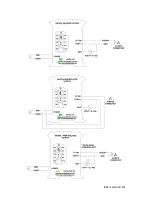
Page 40: ...Ref IS MDUINO XXX Typical Connections ...

Page 41: ...Ref IS MDUINO XXX ...

Page 42: ...Ref IS MDUINO XXX ...

Page 43: ...Ref IS MDUINO XXX ...

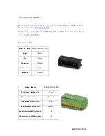
Page 44: ...tor from Phoenix contact FK MC 0 5 10 ST 2 5 Connection details Article reference MC 0 5 10 G 2 5 THT Height 8 1mm Pitch 2 5mm Dimension 22 5mm Pin dimensions 0 8x0 8mm Pin spacing 2 50mm Article reference FK MC 0 5 10 ST 2 5 Rigid conduit section min 0 14 mm Rigid conduit section max 0 5 mm Flexible conduit section min 0 14 mm Flexible conduit section max 0 5 mm Conduit section AWG kcmil min 26 C...

Page 45: ...Ref IS MDUINO XXX Mechanical Characteristics Dimension M duino Family DIN Rail mounting ...

Page 46: ...XX About Industrial Shields Direction Fàbrica del Pont 1 11 Zip Postal Code 08272 City Sant Fruitós de Bages Barcelona Country Spain Telephone 34 938 760 191 34 635 693 611 Mail industrialshields industrialshields com ...

Reviews: