
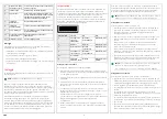

DIP switch
Function
ON
OFF
1
Pairing with sensor
(or transmitter)
Pairing mode
Normal mode
2
Walk test
Walk test mode
Normal mode
3
Factory reset
Clear mode
Normal mode
4
Pairing with
receiver
Pairing mode
Normal mode
5-7
Not used
8
Tamper protection
Disabled
Normal mode
(enabled)
Pairing with receiver
To pair the repeater with the receiver MR32W:
1. In
Normal mode
, slide DIP switch 4 to the ON position to put it into
Pairing mode
. The repeater will emit 1 long beep and the yellow LED will
be lit.
2. Prepare the receiver for pairing according to the documentation for
MR32W.
3. Press the
function button
on the repeater. The repeater will transmit a
test code to the receiver as the red LED lights up and the repeater emits
1 beep.
4. If the repeater receives an acknowledge signal from the receiver within
60 s, the pairing is successful. The blue LED will light up for 1 second as
the repeater emits 1 long beep.
If the repeater fails to receive an acknowledge signal from the receiver
within 60 s, the pairing has failed and is indicated by the yellow LED
flashing 3 times. Repeat the pairing procedure.
5. Slide DIP switch 4 to the OFF position. The repeater will emit 1 long
beep and the yellow LED will turn off as the repeater returns into
Normal
mode
.
After being paired with the receiver, the repeater will automatically transmit
supervisory signals every 30-50 minutes. If the receiver has not received the
supervisory signal for a preset period of time it will set an alarm in the
Modbus register (Sensor Supervisor Error).
Note!
The receiver can use a maximum of 32 channels. Therefore. the to-
tal number of repeaters or sensors and transmitters paired to the receiver
is 32.
Pairing with repeater
To pair
Repeater A
with
Repeater B
:
1. In
Normal mode
, slide DIP switch 1 to the ON position on
Repeater B
to
put it into
Pairing mode
.
Repeater B
will emit 1 long beep and the yellow
LED will flash slowly (1 flash every 2 seconds).
2. Press the
function button
on
Repeater A
, it will emit 1 long beep and the
blue LED will light up for 1 second to indicate successful pairing.
If
Repeater B
receives the pairing signal from
Repeater A
, it will emit 1
long beep and the blue LED will light up for 1 second to indicate
successful pairing.
If
Repeater B
receives the pairing signal from
Repeater A
and
Repeater A
was already paired,
Repeater B
will emit 2 beeps and the blue LED will
light up for 1 second.
3. When the pairing is complete, slide DIP switch 1 of
Repeater B
to the
OFF position.
Repeater B
will emit 1 long beep, the yellow LED will turn
off as
Repeater B
returns to
normal mode
.
Note!
Do not cross-pair the repeaters, i.e. do not pair
Repeater A
with
Re-
peater B
as well as
Repeater B
with
Repeater A
.
All repeaters must also be paired with the receiver, MR32W.
Pairing with a sensor
To pair the repeater with a sensor (or transmitter):
1. In
Normal mode
, slide DIP switch 1 to the ON position to put it into
Pairing mode
. The repeater will emit 1 long beep and the yellow LED will
flash slowly (1 flash every 2 seconds).
2. Send a pairing signal from the sensor according to its documentation
(usually a Test or Pair button is pressed on the sensor).
If the repeater receives a pairing signal from a new sensor, it will emit 1
long beep and the blue LED will light up for 1 second to indicate
successful pairing.
If the repeater receives a pairing signal from a sensor that is already
paired with the repeater, it will emit 2 beeps and the blue LED will light
up for 1 second.
3. When the pairing is complete, slide DIP switch 1 to the OFF position. The
repeater will emit 1 long beep, the yellow LED will turn off as the
repeater returns to
Normal mode
.
Note!
If multiple repeaters are used, only pair sensors with the
repeater(s) closest to the operation areas of the sensors.
All the sensors that are paired with the repeater must also be paired with
the receiver.
Walk test
To put the repeater into
Walk test mode
to check for the signal range with
the sensors (or transmitters) or the receiver:
1. In
Normal mode
, slide DIP switch 2 to the ON position to put it into
Walk
test mode.
The repeater will emit 1 long beep and the yellow LED will
flash (1 flash every second).
2. When the repeater receives signals from the receiver or the paired
sensors, it will emit a long beep and the blue LED will light up for 1
second. The signal is then retransmitted as the red LED lights up for 1
second.
3. To exit
walk test mode
, slide DIP switch 2 to the OFF position. The
repeater will emit 1 long beep and the yellow LED will turn off.
Factory reset
To clear the previously programmed memory and reset the repeater to
factory default:
1. In
Normal mode
, slide DIP switch 3 to the ON position. The repeater will
emit 1 long beep and the yellow LED will light up.
2. Press and hold the
function button
for 5 seconds. The repeater will emit
1 long beep to indicate that all paired sensors and receivers are cleared
from the repeater.
3. To exit
Clear Mode
, slide DIP switch 3 to the OFF position. The repeater
will emit 1 long beep and the yellow LED will turn off.
Tamper protection
The repeater has a tamper protection function which is enabled in
Normal
mode
. The tamper switch is in the normal operating position when the
repeater is hooked onto the wall mounting bracket. Tamper violation
happens when the repeater is removed from the hook and the tamper
switch is released. The tamper protection function can be disabled by sliding
DIP switch 8 to the ON position.
Handling
If the repeater receives a signal from the receiver (e.g. a command), the
signal is retransmitted to the corresponding sensor(s) from the repeater. The
transmission LEDs will light up accordingly.
If the repeater receives a signal from a sensor (e.g. an alarm signal), the
signal is retransmitted to the receiver from the repeater. The transmission
LEDs will light up accordingly.
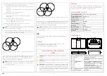
Multiple repeaters
Figure 1 Receiver MR32W, repeaters A, B and C, with RF coverage, and sensor
D
A transmission relay with multiple repeaters, see
, is formed the
following way:
B
C
MR32W
A
D
MRPW
2


