background image

02VJ-004 rev.2

RF Pilot

Wireless remote controller with display

EN

Perenmarkt 10B, 1681PG ZWAAGDIJK-OOST ind.terrein: WFO/ABC THE NETHERLANDS

Tel: +31(0)228-567729, Fax: +31(0)228-567797, Email: info @ wardenaar.com, Internet: www.wardenaar.com

Rabobank 32 69 98 268, KvK te Alkmaar 37079598,  BTW NL 8070.48.768.B01

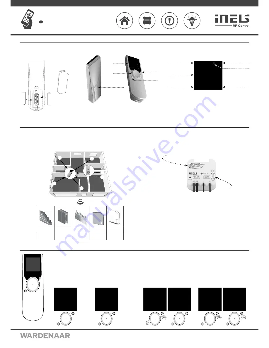
Battery insertion                                                         Device description                                                                                 Display description - basic display

+

-

+

-

Display

Direction
button

Control

button T1

Control

button T2

Time

Date

Current temperature
display

Enter the menu

Quick Control
options

Battery

cover

Low battery

indicator

Remove the battery cover and insert two R03/
AAA batteries as indicated.

Battery

cover

Device

mo 01.01.10               12:54

Favourite 1 
Favourite 2
Favourite 3
Favourite 4
Favourite 5
Favourite 6
Favourite 7

Temp.: 23C                MENU

The memory has an independent power supply. Any custom adjustment (except for time and date) will remain.
After inserting the batteries, the RF Pilot name and the fi rmware number will appear on the initial screen.

Radio frequency signal penetration through various construction materials

Basic Steps for Successful Programming of RF Pilot

Step 1 - Location of RF units

Keep in mind that the radio signal range for RF installations depends on the building structure, materials 
used and the manner of unit location in the area.

Step 2 - Complete the Installation Form

- name of the device you want to control
- names of units (e.g.: RFSA-61B, ...)
- addresses of units (e.g.: 577515, ...)
(The Installation Form is included at the end of the Manual).

Name

Address

E.g.: RFSA-61B

E.g.: 577515

Step 3 - Add actuator
Add

 actuators and their addresses into the Controller memory.

Step 4 - Allocation of actuators to rooms
Allocation

 of actuators to rooms.

Step 5 - Optional setting
Rename

 actuator according to your requirements. 

Test

 of the range and RF signal 

quality. 

Rename

 Room. Create 

Scene

. Saving most frequently used Actuators / Rooms 

/ Scenes in the Initial Screen Favourite as shortcuts.

RF

RP

-2

0

60 - 90 %

80 - 95 %

20 - 60 %

0 - 10 %

80- 90 %

brick walls

wooden structures

with plaster boards

reinforced 

concrete

metal partitions

common 

glass

Controller Activation                                                                                                                                      Settings Menu / Settings - Language

T1

T2

Fig. 3

mo 01.01.10               12:54


Rooms

Scenes

Favourite

EXIT                        SELECT

T1

T2

Fig. 2

mo 01.01.10               12:54

Favourite 1 
Favourite 2
Favourite 3
Favourite 4
Favourite 5
Favourite 6
Favourite 7

Temp.: 23C                MENU

Fig. 1

As standard, the display is in the sleep mode - no information is displayed 
(Fig. 1).
Press any button briefl y to display the 

Initial Screen

 (Fig. 2).

Press T1 to enter the 

Basic Menu

 (Fig. 3).

Note: When using the controller, 10 seconds after pressing any button, the RF Pilot switches 
to the sleep mode. In the Settings Menu, it switches to the sleep mode 40 seconds after 
pressing any button.

Settings Menu

To enter the Settings Menu (Fig. 5), press the left side of the direction button together with the T1 
button (Fig. 4) in the Basic Menu.

T1

mo 01.01.10               12:54


Rooms

Scenes

Favourite

EXIT                       SELECT

Fig. 4

T1

T2

Language

Date and time
Actuators
Rooms
Scenes
Favourite
Device reset

EXIT                        SELECT

Fig. 5

T2

T1

Cestina

Slovencina
English
Deutsch
Magyar
Pyccии яз.
Romana
Polski

EXIT                        SELECT

Fig. 7

T2

T1

Language

Date and time
Actuators
Rooms
Scenes
Favourite
Device reset

EXIT                       SELECT

Fig. 6

Language

Used for language setting. Press T1 (Fig. 6) to enter the Language Menu. Choose the requested 
language using the direction button (Fig. 7). Confirm using the T1 button.

2/8

Summary of Contents for RF Pilot

Page 1: ...the home screen Option of grouping dimmers RFDA 73M RGB where you can place up to 10 units under a single control panel control of over 100 m of colored LED strip Designed in white and anthracite with color OLED display Display of room temperature battery status date and time directly on display Bidirectional communication transmits and receives commands and displays the status of units Thanks to ...

Page 2: ...s into the Controller memory Step 4 Allocation of actuators to rooms Allocation of actuators to rooms Step 5 Optional setting Rename actuator according to your requirements Test of the range and RF signal quality Rename Room Create Scene Saving most frequently used Actuators Rooms Scenes in the Initial Screen Favourite as shortcuts RFRP 20 60 90 80 95 20 60 0 10 80 90 brick walls wooden structures...

Page 3: ... Name Actuator 1 EXIT ASSIGN Fig 2 T1 T2 mo 01 01 10 12 54 Room assigned EXIT ASSIGN Fig 4 T1 T2 Actuator already used Fig 5 T1 T2 mo 01 01 10 12 54 Room 1 Room 2 Room 3 Room 4 Room 5 Room 6 Room 7 EXIT ASSIGN Fig 3 Rename Fig 1 used to name the actuator the name will be displayed in the main menu list The Controller automatically arranges the names of Actuator 1 40 in order in the Add Menu The Re...

Page 4: ...ngs Menu using the direction button to select Scenes Press T1 to enter the menu Fig 1 Using the direction button select the name of the Scene Confirm using the T1 button Fig 2 The following options will be displayed Fig 3 Rename Commands Restart T1 T2 Language Date and time Actuators Rooms Scenes Favourite Device reset EXIT SELECT Fig 1 T1 T2 mo 01 01 10 12 54 Scene 1 Scene 2 Scene 3 Scene 4 Scene...

Page 5: ...ude a requested actuator from a selected room and define its function Fig 4 7 the name of the actuator F will be displayed Scene you can include the requested scene to Favourites multiple actuators are controlled by a single press Fig 19 10 Cancel used to delete actuators scenes The Favourite name will be reset to factory setting Fig 11 T1 T2 mo 01 01 10 12 54 Name Lighting Assign Cancel BACK SELE...

Page 6: ...h On Switch Off Brightness 0 Gradual switch ON Gradual switch OFF Setting BACK PROCEED Fig 2 Actuator Function 6 8 Actuator RFSA 11B RFSA 6xM RFJA 12B RFDA 11B RFDA 71B Pressing the directional button left Switch Off Switch Off Simulation of the button on the key chain tilting the roll up blinds Press and hold to send the roll up blinds up Switch Off Switch Off Pressing the directional button right Sw...

Page 7: ...nes Favourite EXIT SELECT Fig 1 T1 T2 mo 01 01 10 12 54 Lamps Favourite 2 Favourite 3 Favourite 4 Favourite 5 Favourite 6 Favourite 7 Temp 23C MENU Fig 2 What to do when RF Touch Unit Warnings Warning is displayed in case of incorrect entry Wait approx 1s between individual button presses 7 8 RFDA 73M RGB Switch On Switch Off Brightness White RGB Description Switching to 100 according to selected c...

Page 8: ...do not mix battery types When inserting the batteries always check their polarity as displayed in the battery compartment Beschädigung des Geräts Schützen Sie das Gerät vor Feuchtigkeit Verwenden Sie das Gerät nur in trockenen Roomsn und niemals im Außenbereich oder in der Nähe von Flüssigkeiten Achten Sie darauf dass die Fernbedienung während des Betriebs nicht nass feucht oder anderweitig beschä...

Reviews: