C-COM Satellite Systems Inc.
Page 56 of 164
7.6.4.3. MB
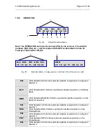
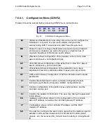
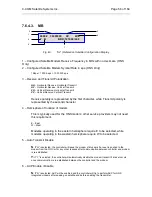
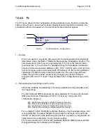
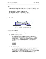
Fig. 40:
“S2” (Reference Satellite) Configuration Display
1 – Configured Satellite Modem Receive Frequency in MHz with no decimals. (HNS
Only)
2 – Configured Satellite Modem Symbol Rate in sps. (HNS Only)
1Msps = 1000 Ksps = 1 000 000 sps
3 – Receive and Transmit Polarization.
HH
– Horizontal Receive, Horizontal Transmit
HV
– Horizontal Receive, Vertical Transmit
VH
– Vertical Receive, Horizontal Transmit
VV
– Vertical Receive, Vertical Transmit
Receive polarity is represented by the first character, while Transmit polarity is
represented by the second character
4 – Hemisphere of location of modem.
This is typically used for the HNS modem; other service providers may not need
this requirement.
E – East
W – West
Modems operating in the eastern hemisphere require E to be selected, while
modems operating in the western hemisphere require W to be selected.
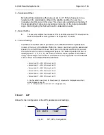
5 – Auto Transmit Disable
N
: If “N” is selected, the controller will leave the modem status as is if a reset is pushed to the
modem from the NOC or for any other reasons after communication between controller and modem
is re-established.
Y
:
If “Y” is selected, the controller will automatically disable the modem transmit if a reset occurs
once communication is re-established between the controller and the modem.
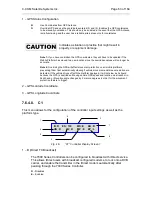
6 – ACP Enable / Disable
N
: If “N” is selected, ACP will be enabled and the controller will try to perform ACP for HNS
integrated modems after peaking on satellite and before enabling the transmitter.
0990.0 30000000 HV W/E
Y N BRR :1210.99/22.0
1
4
2
3
5
6
7


