
5
14
15
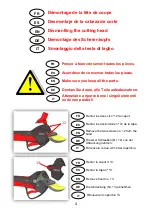
FR
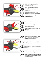
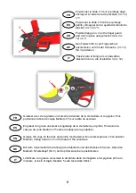
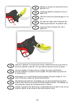
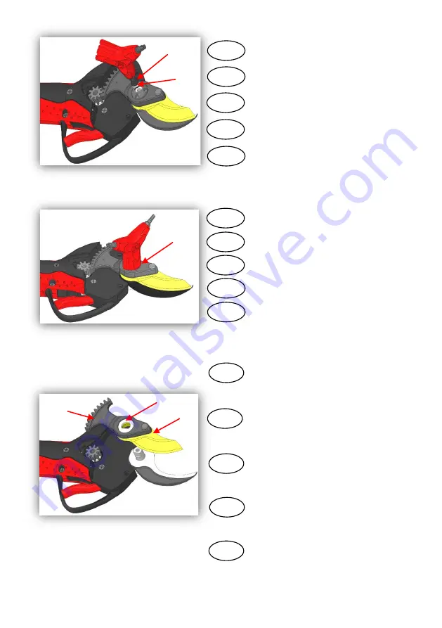
Retirer la vis de blocage n°14 et la
rondelle plastique n°15.
ES
EN
DE
IT
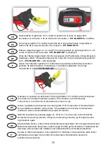
Retirer l’écrou de lame n°16.
FR
ES
EN
DE
IT
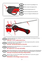
16
Retirer l’ensemble crémaillère n°17, lame
n°18 et rondelle n°19. Si nécessaire,
nettoyer le pourtour du pignon.
FR
17
19
18
ES
EN
DE
IT
Retirar el tornillo de tope nº14 y la
arandela plástica n°15.
Retirar la tuerca de la hoja n°16.
Retirar el conjunto cremallera nº17, hoja
nº18 y arandela nº19. Si necesario, limpiar
el contorno del piñón.
Remove locking bolt no. 14 and plastic
washer no. 15.
Remove blade screw no. 16.
Remove rack mechanism no. 17, blade no. 18
and washer no.19. Clean around the pinion if
necessary.
Die Mutter des Schneidmessers (Nr. 16)
abnehmen.
Rimuovere la vite di bloccaggio 14 e la
rondella di plastica 15.
Rimuovere il dado della lama 16.
Rimuovere l’insieme cremagliera 17,la lama
18 e la rondella 19. Se necessario, pulire il
perimetro del pignone.
Die Konterschraube (Nr. 14) und die
Kunststoff U-Scheibe (Nr. 15) abnehmen.
Das Zahnrad (Nr.17), das Schneidmesser
(Nr.18) und die U-Scheibe (Nr.19) abnehmen.
Bei Bedarf das Ritzel reinigen.