


9
7
6
8
FR
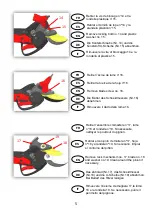
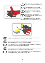
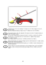
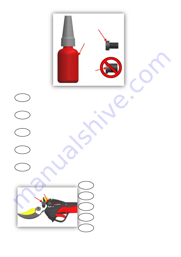
Visser les vis n°6 et n°7 au crochet.
ES
EN
DE
IT
7
6
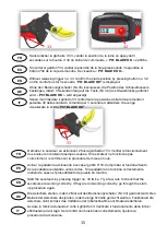
FR
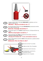
A l’aide du tube de colle n°8, imprégner
UNIQUEMENT
les filets de la vis n°6 en
retirant le surplus de colle.
Attention : Ne pas encoller la vis n°7
ES
EN
DE
IT
Con ayuda del tubo de cola nº8, impregnar
ÚNICAMENTE
las roscas de los tornillos
nº6 y retirar el exceso de cola.
Atención: No pegar el tornillo nº7
Atornillar el tornillo nº6 y nº7 al gancho.
Use the tube of glue no. 8 to fill
ONLY
the thread of bolt no. 6 with glue. Remove any
surplus.
N.B. Do not put glue on bolt no. 7
Screw bolt nos. 6 and 7 to the hook.
Mit der Klebstofftube (Nr.8)
NUR
das Gewinde der Schraube (Nr. 6) benetzen.
Überflüssigen Klebstoff bitte entfernen.
Achtung: Die Schraube (Nr. 7) nicht mit Klebstoff versehen.
Die Schrauben (Nr. 6 und 7) an die
Gegenklinge montieren.
Usare la colla 8 badando a spalmarla
SOLO
sul filetto della vite 6 e pulendo eventuale
eccesso di colla.
Attenzione: Non incollare la vite 7
Stringere le viti 6 e 7 sul gancio.


