XC2200 Derivatives
System Units (Vol. 1 of 2)
Memory Organization
User’s Manual
3-56
V2.1, 2008-08
MemoryX2K, V1.3
Interrupt Control
Interrupt control and status.
Reset by Application Reset.
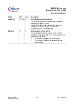
RPA
[3:2]
rh
Read Protection Activated
“01”: Short notation RPA = 1. The read protection of
the flash memory is activated.
“10”: Short notation RPA = 0. The read protection is
not activated.
“00” | “11”: Illegal state. Same effect as “01”. The
illegal state can only be left by an Application
Reset.
This field is only changed by the IMB Core. Software
writes are ignored.
PSPROT
[15:8]
rw
PSRAM Write Protection
This 8-bit field determines the address up to which
the PSRAM is write protected.
The start address of the writable range is E0’0000
H
+ 1000
H
*PSPROT. The end address is determined
by the implemented memory. The equivalent range
in the PSRAM area with flash access timing is
protected as well. Here the writable range starts at
E8’0000
H
+ 1000
H
*PSPROT and ends at E8’FFFF
H
for XC2200.
So with PSPROT=00
H
the complete PSRAM is
writable. In case of XC2200 with PSPROT=10
H
or
bigger the complete implemented PSRAM is write-
protected.
IMB_INTCTR
Interrupt Control
ISFR (FF FF04
H
)
Reset value: 0000
H
15
14
13
12
11
10
9
8
7
6
5
4
3
2
1
0
ISR
PSE
R
–
–
–
PSE
RCL
R
ISET ICLR
–
–
–
–
DPR
OTR
P
DDD
TRP
DIDT
RP
IEN
rh
rh
–
–
–
w
w
w
–
–
–
–
rw
rw
rw
rw
Field
Bits
Typ Description


