XC2200 Derivatives
System Units (Vol. 1 of 2)
Interrupt and Trap Functions
User’s Manual
5-24
V2.1, 2008-08
ICU_X2K, V2.2
5.4.2
The PEC Source and Destination Pointers
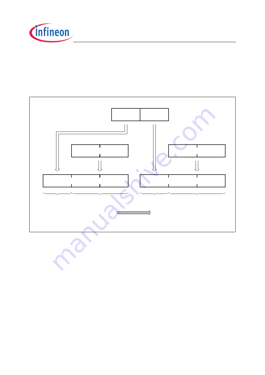
The PEC channels’ source and destination pointers specify the locations between which
the data is to be moved. Both 24-bit pointers are built by concatenating the 16-bit offset
register (SRCPx or DSTPx) with the respective 8-bit segment bitfield (SRCSEGx or
DSTSEGx, combined in register PECSEGx).
Figure 5-3
PEC Data Pointers
When a PEC pointer is automatically incremented after a transfer, only the offset part is
incremented (SRCPx and/or DSTPx), while the respective segment part is not modified
by hardware. Thus, a pointer may be incremented within the current segment, but may
not cross the segment boundary. When a PEC pointer reaches the maximum offset
(FFFE
H
for word transfers, FFFF
H
for byte transfers), it is not incremented further, but
keeps its maximum offset value. This protects memory in adjacent segments from being
overwritten unintentionally.
No explicit error event is generated by the system in case of a pointer saturation;
therefore, it is the user’s responsibility to prevent this condition.
Note: PEC data transfers do not use the data page pointers DPP3 … DPP0.
Unused PEC pointers may be used for general data storage.
x = 7 … 0, depending on PEC channel number
MCD04916
Source Pointer
23
16 15
0
Segment Address
Segment Offset
Destination Pointer
23
16 15
0
Segment Address
Segment Offset
SRCPx
15
0
SRCPx
DSTPx
15
0
DSTPx
DSTSEGx
7
0
SRCSEGx
15
8
PECSEGx
Data Transfer


