XC2200 Derivatives
System Units (Vol. 1 of 2)
System Control Unit (SCU)
User’s Manual
6-28
V2.1, 2008-08
SCU, V1.13
6.1.7.4
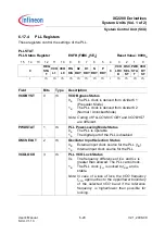
PLL Registers
These registers control the settings of the PLL.
PLLSTAT
PLL Status Register
ESFR (F0BC
H
/5E
H
)
Reset Value: 0000
H
15
14
13
12
11
10
9
8
7
6
5
4
3
2
1
0
0
REG
STA
T
VCO
L1
VCO
L0
FIN
DIS
K2
RDY
K1
RDY
N
RDY
P
RDY
0
VCO
LOC
K
OSC
SEL
ST
PWD
STA
T
VCO
BY
ST
r
rh
rh
rh
rh
rh
rh
rh
rh
r
rh
rh
rh
rh
Field
Bits
Type
Description
VCOBYST
0
rh
VCO Bypass Status
0
B
The PLL clock is derived from divider K1
(Prescaler Mode)
1
B
The PLL clock is derived from divider K2
(Normal / Unlocked Mode)
Note: Coding of PLLCON0.VCOBY and VCOBYST
are different.
PWDSTAT
1
rh
PLL Power-saving Mode Status
0
B
The PLL is operable
1
B
The digital part of the PLL is disabled
OSCSELST
2
rh
Oscillator Input Selection Status
0
B
External input clock source for the PLL (
f
IN
)
1
B
Internal input clock source for the PLL
VCOLOCK
3
rh
PLL VCO Lock Status
0
B
The frequency difference of
f
REF
and
f
DIV
is
greater than allowed. The PLL cannot lock.
1
B
The PLL clock
f
PLL
is locked to
f
REF
and is
stable.
Note: In case of a loss of lock, the VCO frequency
f
VCO
approaches to the upper/lower boundary
of the selected VCO band if the reference
frequency is higher/lower than possible for
locking.


