XC2200 Derivatives
System Units (Vol. 1 of 2)
System Control Unit (SCU)
User’s Manual
6-34
V2.1, 2008-08
SCU, V1.13
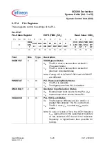
PLLCON1
PLL Configuration 1 Register ESFR (F1BA
H
/DD
H
)
Reset Value: 000A
H
15
14
13
12
11
10
9
8
7
6
5
4
3
2
1
0
P
ACK
0
PDIV
0
EM
FIN
DIS
EN
EM
CLK
EN
0
A
OSC
SEL
RES
LD
OSC
SEL
PLL
PWD
rw
r
rw
r
rw
rw
r
rw
w
rw
rw
Field
Bits
Type
Description
PLLPWD
0
rw
PLL Power Saving Mode
0
B
Normal behavior
1
B
Complete PLL block is put into a power saving
mode and no longer operates
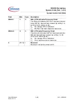
OSCSEL
1
rw
Oscillator Input Selection
0
B
Select external clock as input for PLL
1
B
Select trimmed current controlled clock as
input for PLL
RESLD
2
w
Restart VCO Lock Detection
Setting this bit will reset bit PLLSTAT.VCOLOCK and
restart the VCO lock detection.
AOSCSEL
3
rw
Asynchronous Oscillator Input Selection
This bit overrules the setting of bit OSCSEL.
0
B
Configuration is controlled via bit OSCSEL
1
B
Select asynchronously trimmed current
controlled clock as input for PLL
EMCLKEN
5
rw
VCOLCK Emergency System Clock Source
Select Enable
This bit requests the master clock multiplexer (MCM)
to switch to an alternate clock (selected by bit field
SYSCON0.EMCLKSEL) in a VCOLCK emergency
case.
0
B
MCM remains controlled by
SYSCON0.CLKSEL
1
B
MCM is controlled by SYSCON0.EMCLKSEL


