Application Note
14 of 36
002-34970 Rev. **
2022-05-03
Foreign object detection tuning guide for wireless power transmitters
Applicable for WLC ICs
FOD parameter tuning
3
FOD parameter tuning
FOD parameter tuning
is required when the reference design of the WLC power transmitter is changed. The
following changes from the WLC power transmitter reference design will result in a need to retune the FOD:
1.
Transmitter coil used in the design
2.
Change in any shielding or packaging of the transmitter coil
3.
Spacing between coil and interface surface (Z-height)
These lead to changes in the Q factor and/or resonance frequency and/or system power loss measurements.
Tuning FOD by updating the configuration parameters optimizes the FOD functionality for custom designs.
FOD parameter tuning
includes the process of data collection, calculating the appropriate parameters, and
updating these parameters in the Wireless Charging Configuration Utility.
Data collection
and
calculation
of parameter values use the
FOD_TuningGuide_Calculator.xlsx
as a supporting
document.
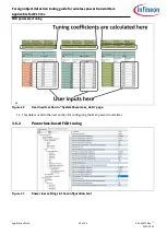
This tuning calculator provides the following worksheets that require user input:
•
SystemPowerLoss_data: Input data for power loss FOD parameter calculations is collected here. The
coefficients calculated here are used for configuring the WLC power transmitter.
•
QF Scaling Factor Calc: Q factor
tuning data is collected in the “User Inputs” section in this page.
The
calculations section gives the parameter values for Q factor tuning based on user inputs.
•
RF Scaling_Threshold Calc: The RF-based data is
collected in the “User Inputs” section. The scaling
factor and threshold frequency are auto-generated based on the user data.
Wireless Charging Configuration Utility
will save the configurations to the WLC power transmitter. These
calculations are taken from
FOD_TuningGuide_Calculator.xlsx
.
The tuning process requires a WPC-approved compliance tester tool setup. The following sections discuss the
tools required and the steps to prepare the setup. Use
FOD_TuningGuide_Calculator.xlsx
to enter the data from
the setup to auto-generate the tuning parameters.
3.1
Tuning objectives
The following are the desired objectives for optimal FOD system performance:
•
Scaling factor and threshold tuning for FOD using Q factor
•
Scaling factor and threshold tuning for FOD using resonance frequency
•
System power loss curve coefficient tuning
As discussed in section
, the system power loss curve coefficients relate the reported receiver power to the
calibrated transmitter power and hence improve the reliability of the FOD mechanism. The reported Q factor
and resonance frequency is measured using a MP-A1 transmitter coil. However, the transmitter may have any
other coil in its design and so the reference values of Q factor have to be scaled (or converted) to the
corresponding coil type. The scaling factor is a conversion constant factor to calculate Q factor values for the
transmitter designed without a MP-A1 coil. Refer to
for more details on the Qi Standard FOD mechanisms.


