Application Note
18 of 36
002-34970 Rev. **
2022-05-03
Foreign object detection tuning guide for wireless power transmitters
Applicable for WLC ICs
FOD parameter tuning
3.4.1
Q factor scaling and threshold tuning process
The Q factor scaling derives the reference Q factor for the WLC power transmitter from the receiver-reported
reference Q factor. The WLC power transmitter uses two scaling factors.
•
Q-high scale factor: Used for scaling the reference Q factor by the TPRs without friendly metals. The EPP
TPRs, without friendly metal, will report the reference Q factor greater than 100.
•
Q-low scale factor: Used for scaling the reference Q factor by the TPRs with friendly metals. The EPP
TPRs, with friendly metal, will report the reference Q factor less than 100.
The following steps should be followed to tune the Q scaling factor:
1.
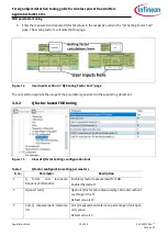
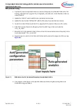
Capture the receiver-reported reference Q factor for all the EPP TPRs on the
“
QF Scaling Factor Calc
”
page of the supporting document under the “
Q factor
Scaling with TPRs without Friendly Metals”
table
for the following TPRs:
a.
TRP#MP3
b.
TPR#MP4
c.
TPR#7
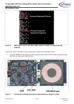
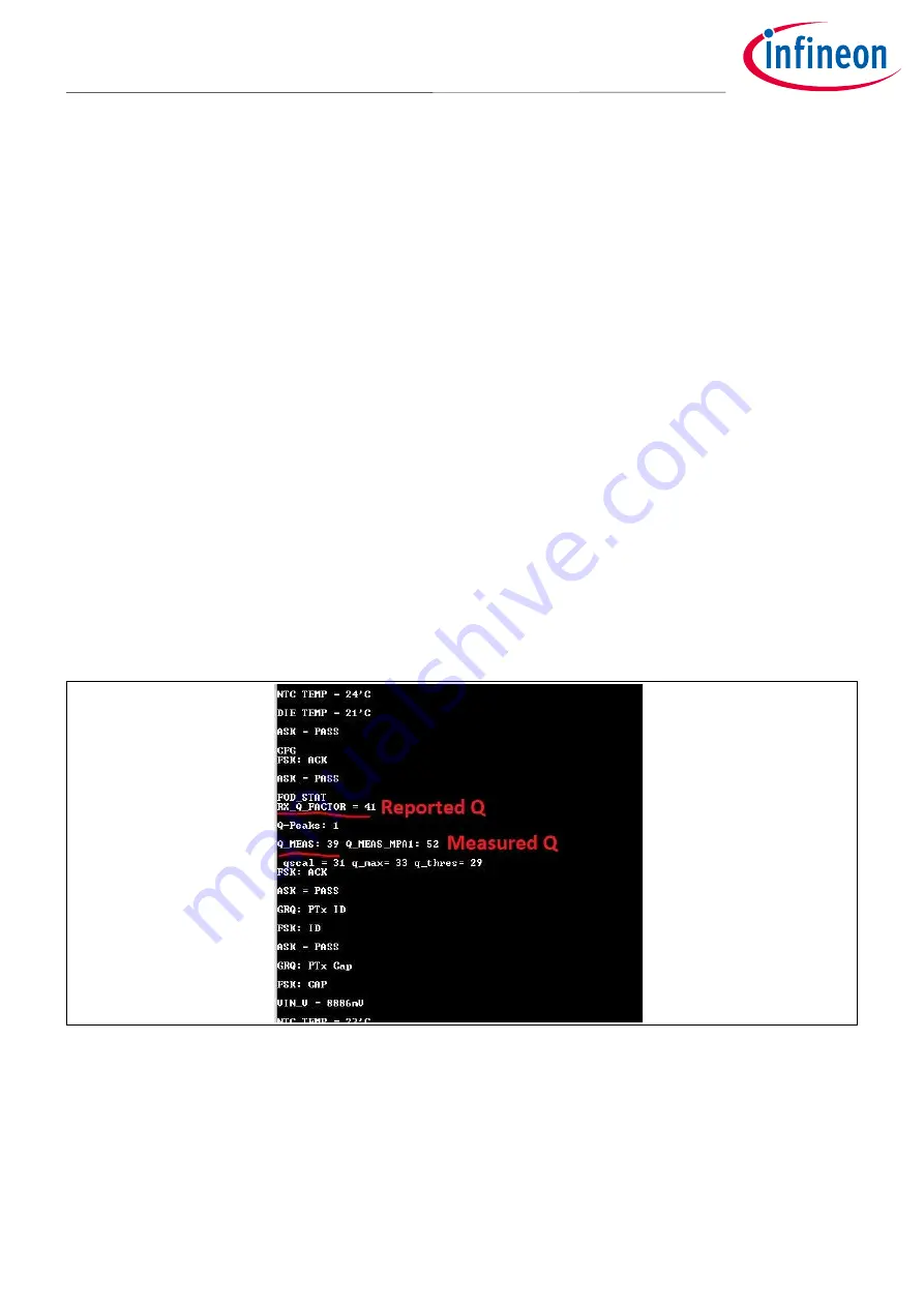
for the UART logs for receiver-reported reference Q factor.
2.
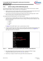
Capture the measured Q value by the WLC power transmitter with all the EPP TPRs listed below. Ensure
no foreign object is present on the interface surface during these measurements. See
UART logs for the WLC-measured Q factor.
Figure 13
UART logs for receiver-reported and WLC power transmitter measured Q factor
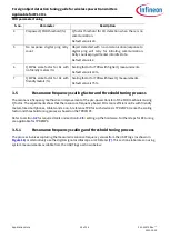
3.
Record h
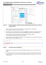
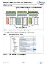
igh scaling factor from “
QF Scaling Factor Calc
” and update the
Wireless Charging
Configuration Utility parameters. Refer to section
for more details.
4.
Repeat Steps 1 through 3 with Q factor scaling with TPRs without friendly metals.


