CY8CKIT-064S0S2-4343W PSoC 64 Standard Secure – AWS Wi-Fi BT Pioneer Kit Guide, Doc. # 002-30680 Rev. *B
10
Introduction
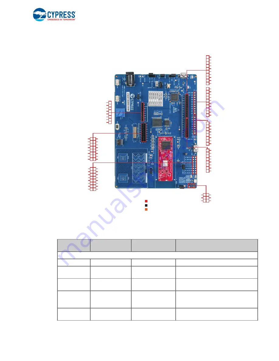
shows the pinout of the PSoC 64 Standard Secure – AWS Wi-Fi BT Pioneer Board.
Figure 1-2. PSoC 64 Standard Secure – AWS Wi-Fi BT Pioneer Board Pinout
Table 1-1. PSoC 64 Standard Secure – AWS Wi-Fi BT Pioneer Board Pinout
Pin
Primary On-board
Function
Secondary On-board
Function
Connection details
PSoC 64 MCU Pins
XRES
Hardware Reset
–
–
P0[2]
GPIO on non-Arduino
header IO0 (J22.1)
–
–
P0[3]
GPIO on non-Arduino
header IO1 (J22.2)
–
–
P0[4]
User button with
Hibernate wakeup
capability
GPIO on non-Arduino
header (J21.9)
–
P0[5]
RGB green LED
(LED5)
GPIO on non-Arduino
header (J24.3)
–
BT_UART_RXD
BT_UART_TXD
BT_UART_CTS
BT_UART_RTS
NC
NC
WL_GPIO_4
NC
BT_I2S_CLK
BT_I2S_WS
BT_I2S_DO
BT_I2S_DI
NC
BT_IO3
BT_IO4
BT_IO5
Arduino Uno R3
LEGEND
PSoC 6 I/Os
WL/BT I/Os
NC
VTRAG/
IOREF
XRES/
RESET
V 3.3/
3.3V
V 5.0/
5V
GND/
GND
GND/
GND
VIN/
Vin
P6_0/
SCL
P6_1/
SDA
VREF/
AREF
GND/
GND
P12_2/
D13
P12_1/
D12
P12_0/
D11
P12_3/
D10
P7_6/
D9
P7_5/
D8
P5_7/
D7
P5_6/
D6
P5_5/
D5
P5_4/
D4
P5_3/
D3
P5_2/
D2
P5_1/
D1
P5_0/
D0
P1_4
P0_4
P7_4
NC
NC
NC
NC
NC
NC
NC
NC
P13_5
P13_4
P8_0
P13_6
P1_3
P0_3
P0_2
P10_0/
A0
P10_1/
A1
P10_2/
A2
P10_3/
A3
P10_4/
A4
P10_5/
A5
P10_6
P10_7
P9_0
P9_1
P9_2
P9_3
P9_4
P9_5
P9_6
P9_7
P1_5
P11_1
NC
P1_1
P0_5
P7_3


