CY8CKIT-064S0S2-4343W PSoC 64 Standard Secure – AWS Wi-Fi BT Pioneer Kit Guide, Doc. # 002-30680 Rev. *B
21
Kit Operation
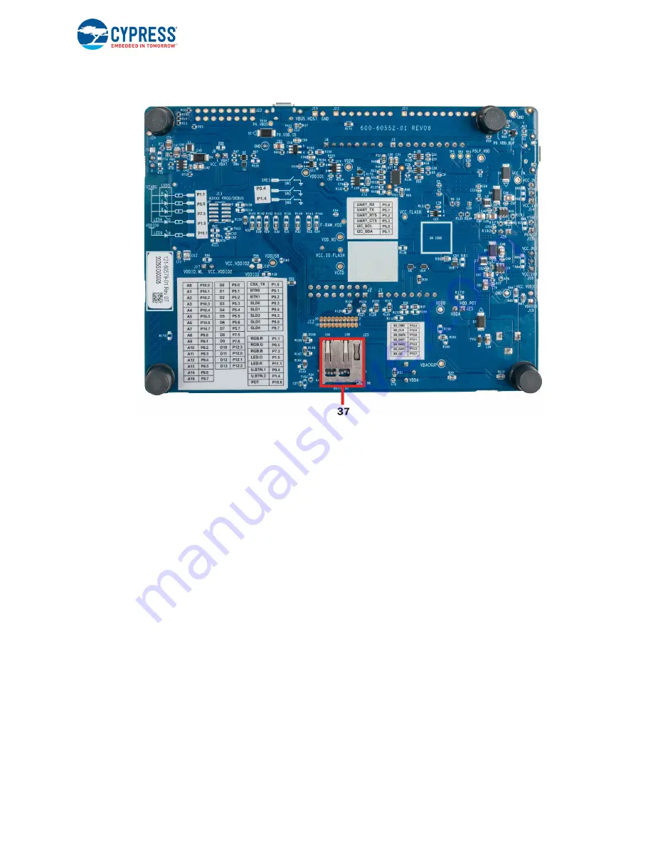
Figure 2-5. PSoC 64 Standard Secure – AWS Wi-Fi BT Pioneer Board - Bottom View
The PSoC 64 Standard Secure – AWS Wi-Fi BT Pioneer Board has the following peripherals:
1.
Power LED (LED1):
This Yellow LED indicates the status of power supplied to board.
2.
KitProg3 USB connector (J6):
The USB cable provided along with the PSoC 64 Standard
Secure – AWS Wi-Fi BT Pioneer Board connects between this USB connector and the PC to use
the KitProg3 onboard programmer and debugger and to provide power to the board.
3.
PSoC 64 MCU VDD power selection jumper (J14):
This jumper is used to select the PSoC 64
MCU VDD supply voltage between 1.8 V and 3.3 V. During provisioning, this jumper must be in
the 3.3 V position and J26 must be removed. This provides 2.5 V to the PSoC 64 VDD which is
required to blow eFuses.
4.
KitProg3 programming mode selection button (SW3):
This button can be used to switch
between various modes of operation of KitProg3 (CMSIS-DAP BULK, CMSIS-DAP HID or
DAPLink modes). For more details, see the
5.
PSoC 64 MCU VDD current measurement jumper (J15):
An ammeter can be connected to this
jumper to measure the current consumed by the PSoC 64 MCU VDD power domain.
6.
PSoC 64 MCU VDD select jumper (J26):
This jumper is used to change VCC_3V3 to 2.5 V.
When jumper shunt is present, VCC_3V3 is 3.3 V and when removed, it is 2.5 V. This is needed
for provisioning. The kit is not intended to be used at 2.5 V during normal operation.
7.
PSoC 64 MCU VDDIO2 and CYW4343W VDDIO power selection jumper (J16):
This jumper is
used to select the PSoC 64 MCU VDDIO2 and CYW4343W VDDIO supply voltage between
1.8 V and 3.3 V. The default value is 1.8 V.
8.
PSoC 64 MCU VDDIO0 current measurement jumper (J19):
An ammeter can be connected to
this jumper to measure the current consumed by the PSoC 64 MCU VDDIO0 power domain. This
is not loaded by default.


