


CY8CKIT-064S0S2-4343W PSoC 64 Standard Secure – AWS Wi-Fi BT Pioneer Kit Guide, Doc. # 002-30680 Rev. *B
23
Kit Operation
26.
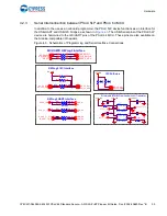
Cypress serial Ferroelectric RAM (CY15B104QSN, U4):
The CY15B104QSN is a 4-Mbit non-
volatile memory employing an advanced ferroelectric process. F-RAM is nonvolatile and per-
forms reads and writes similar to a RAM. It provides reliable data retention for 151 years and is
connected to the Quad SPI interface of the PSoC 64 MCU.
27.
CYW4343W VBAT current measurement jumper (J8):
An ammeter can be connected to this
jumper to measure the current consumed by the CYW4343W VBAT power domain.
28.
CYW4343W VBAT power selection jumper (J9):
This jumper is used to select the CYW4343W
VBAT supply voltage between 1.8 V, 3.3 V and 3.6 V. This board supports VBAT voltages of
3.3 V and 3.6 V. VBAT is 3.3 V when the jumper is not inserted and 3.6 V when the jumper is
inserted.
29.
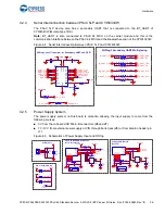
PSoC 64 MCU user LEDs (LED8 and LED9):
These two user LEDs can operate at the entire
operating voltage range of the PSoC 64 MCU. The LED is active LOW, so the pins must be
driven to ground to turn ON the LED.
30.
PSoC 64 MCU I/O headers (J21, J22, J24):
These headers provide connectivity to PSoC 64
MCU GPIOs that are not connected to the Arduino compatible headers. Some of these I/Os are
also connected to on-board peripherals see
not loaded by default.
31.
RGB LED (LED5):
This onboard RGB LED can be controlled by the PSoC 64 MCU. The LEDs
are active LOW, so the pins must be driven to ground to turn ON the LEDs.
32.
Wi-Fi/BT GPIO header (J23):
This header brings out a few I/Os of the CYW4343W for general
purpose applications. This is not loaded by default.
33.
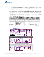
PSoC 64 MCU USB device connector (J7):
The USB cable provided with the PSoC 64
Standard Secure – AWS Wi-Fi BT Pioneer Kit can be connected between this USB connector
and the PC to use the PSoC 64 MCU USB device applications.
34.
Optional USB Host power supply header (J10):
This header provides an option to supply
external power to the PSoC 64 MCU USB when used as a USB Host. This is not loaded by
default.
35.
KitProg3 status LED (LED2):
This Yellow LED indicates the status of KitProg3. The KitProg3
mode is selected using Mode Select button SW3. For details on the KitProg3 status, see the
.
36.
KitProg3 (PSoC 5LP) programmer and debugger (CY8C5868LTI-LP039, U2):
The PSoC 5LP
device (CY8C5868LTI-LP039) serving as KitProg3 is a multi-functional system which includes a
SWD programmer, debugger, USB-I2C bridge and USB-UART bridge. For more details, see the
.
37.
microSD Card holder (J20):
Provide SDHC interface with microSD cards with the option to
detect the presence of the card.
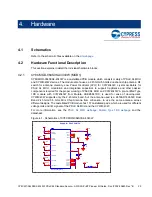
See
Hardware Functional Description on page 29
for details on various hardware blocks.


