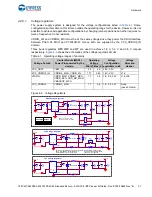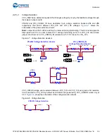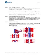
CY8CKIT-064S0S2-4343W PSoC 64 Standard Secure – AWS Wi-Fi BT Pioneer Kit Guide, Doc. # 002-30680 Rev. *B
42
Hardware
4.2.8
LEDs
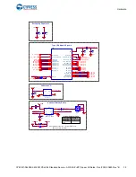
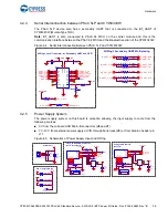
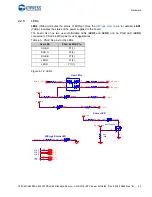
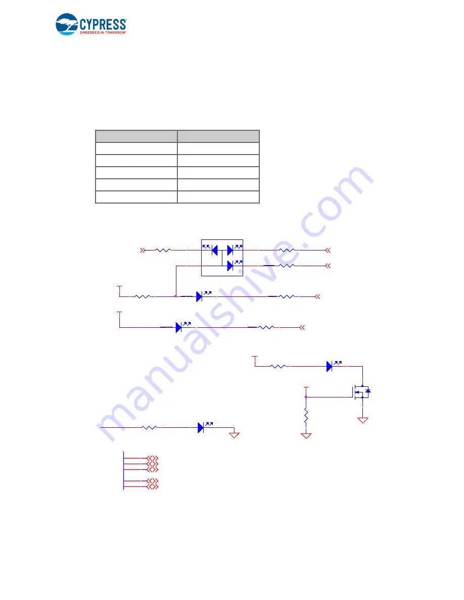
LED2
(Yellow) indicates the status of KitProg3 (See the
LED1
(Yellow) indicates the status of the power supplied to the board.
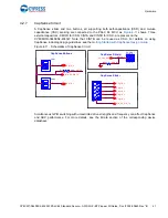
The board also has two user-controllable LEDs (
LED8
and
LED9
) and an RGB LED (
LED5
)
connected to PSoC 64 MCU pins for user applications.
RGB.R
P1[1]
RGB.G
P0[5]
RGB.B
P7[3]
LED.O
P1[5]
LED.R
P11[1]
Figure 4-12. LEDs
Table 4-3. PSoC 64 pins for the LEDs
User LED
PSoC 64 MCU Pin
O_LED_L
R23
100 OHM
R_LED_L
R16
270 OHM
P6_VDD
R100
330 OHM
User LEDs
RGB_G_LED_L
RGB_R_LED_L
R
G
B
LED5
RGB LED
1
2
3
4
RGB_B_LED_L
R15
750 OHM
R101
0 OHM
VDDIO0
R22
1K
LED9
RED
LED8
ORANGE
KitProg3 Status LED
P5LP1_4
LED2
Y ELLOW
R10
750 OHM
LED1
Y ELLOW
Q3
NX3020NAKW,115
D
G
S
R91
390 OHM
P6_VDD_BUF
R64
100K
VCC_3V3
Power LED
P11_1
RGB_R
123
RGB_G
132
RGB_B
26
LED_1
126
LED 2
69
P0_5
P1_5
P7_3
P1_1


