User Guide
17 of 32
002-29388 Rev. *B
2022-06-15
EZ-
PD™ BCR HPI Utility user guide
EZ-
PD™ BCR HPI Utility
2.6
Demo: BCR sink PDOs configuration
The BCR device supports the following two Sink PDOs by default. In
Variable Sink PDO
, the ‘Minimum Required
Voltage’, ‘Maximum Required Voltage’ and ‘Required Operating Current’ are determined by Pin 1 (VBUS_MIN),
Pin 2 (VBUS_MAX), Pin 5 (ISNK_COARSE), and Pin 6 (ISNK_FINE) using a resistor divider. See
•
Fixed, 5 V, [Required operating current]
•
Variable, [Minimum required voltage] ~ [Maximum required voltage], [Required operating current]
Change the Sink PDOs based on your system requirements. This section provides a simple example of how to
configure BCR Sink PDOs.
Note:
1.
All settings for the power contracts are volatile. If power is recycled/removed, the contract goes back to default
values.
2.
Instructions in
Demo: BCR sink PDOs configuration
use CY4533 EZ-
PD™ BCR EVK
using the CYPD3177 device.
3.
The specific pin information is related to the CYPD3177 device only. The BCR-PLUS device has a different pin
map; see the BCR-PLUS datasheet.
2.6.1
Identify BCR’s sink PDOs
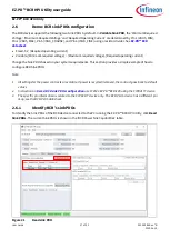
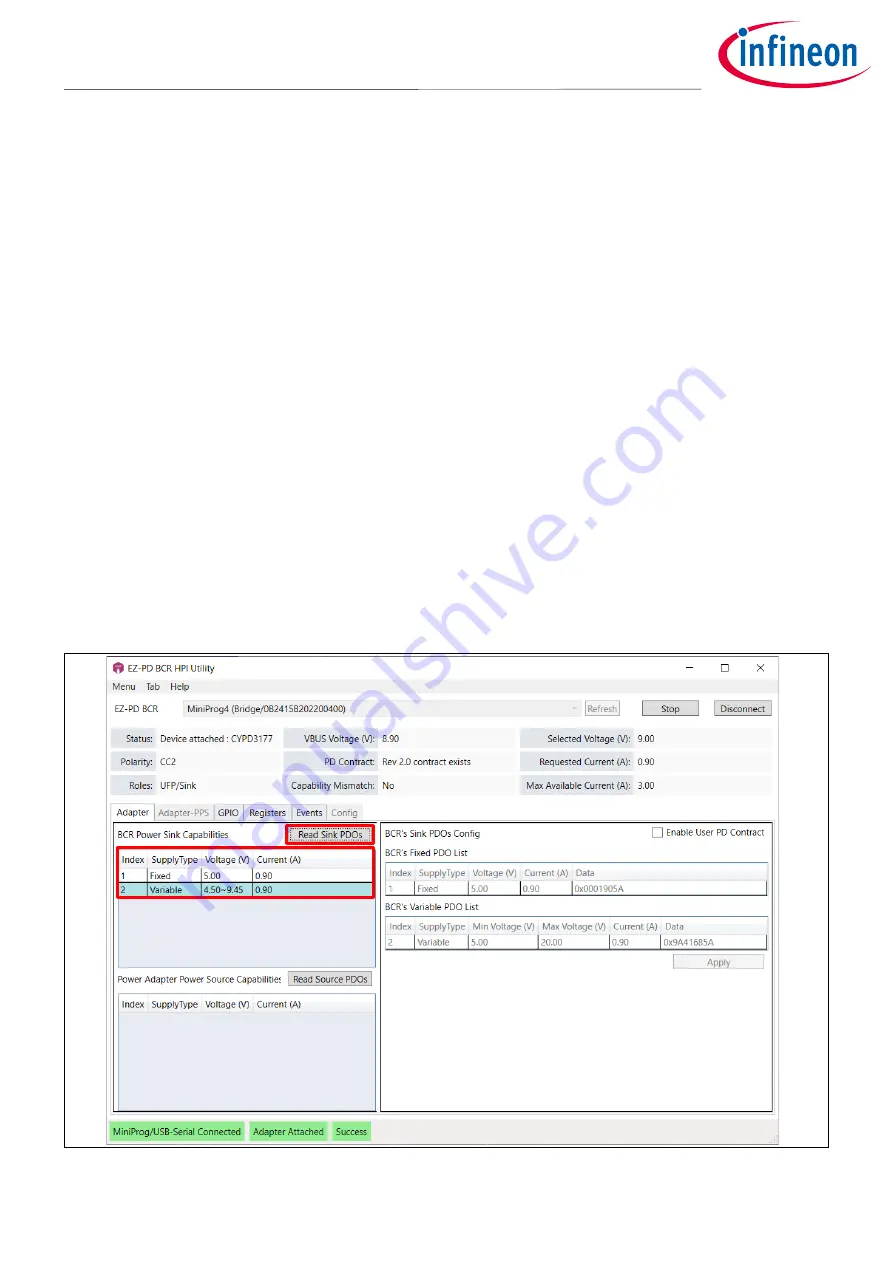
To identify the Sink PDOs of the BCR device connected to the PC running the EZ-PD
™
BCR HPI Utility, click
Read
Sink PDOs
. The current Sink PDOs is shown in the ‘BCR Power Sink Capabilities’ table.
Figure 21
Read sink PDO


