User Guide
9 of 32
002-29388 Rev. *B
2022-06-15
EZ-
PD™ BCR HPI Utility user guide
EZ-
PD™ BCR HPI Utility
2.3
Connection and status bar
The
Connect
button in
helps to establish MiniProg3 or MiniProg4 or USB-to-I2C connection and
enable communication via HPI if the hardware is configured correctly as shown in
and
and is
ready to use.
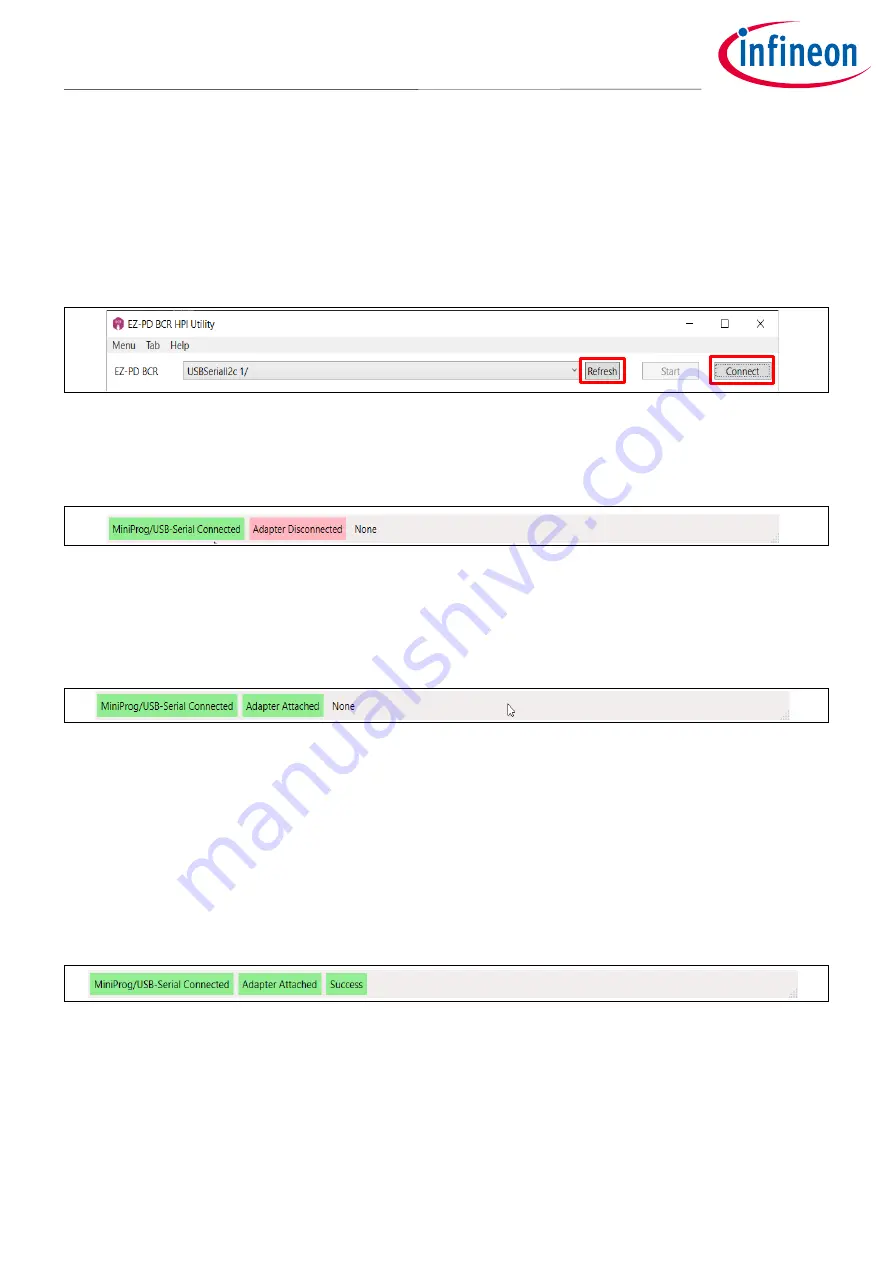
When the MiniProg3 or MiniProg4 is connected to your PC, you can see that GUI detects it as below: Click
Refresh
to update the current available USB-to-I2C connection list.
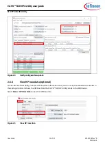
Figure 10
Available connection displayed in GUI
Click
Connect.
MiniProg3/MiniProg4 or USB-I2C connection status is reflected in the status bar.
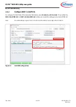
Figure 11
Connection status
Click
Start
to initiate HPI communication between the GUI and the BCR device. The Status bar will update to
reflect the connected power adapter status. The GUI is now ready to communicate with the BCR device and
obtain more information about the connection (between the BCR device and power source PD controller).
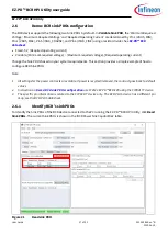
Figure 12
Adapter attached and HPI Established
The third item in the Status bar also shows the result of the last HPI communication. When the EZ-PD
™
BCR HPI
Utility is initially launched, the default status is shown as
“None”. When you
use the EZ-PD
™
BCR HPI Utility to
retrieve information from the connected BCR device, the status of the last request will be updated accordingly
in the Status bar. The status could be one of the following:
•
Success
: HPI communication succeeded and BCR responded with the relevant response code
•
No response
: HPI communication succeeded but BCR did not respond
•
Failure
: HPI communication failed
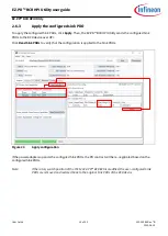
Figure 13
Status bar for HPI communication
Note that there will be a delay of 3-seconds in the Status Bar on MiniProg3 disconnection depending on the
MiniProg3 polling speed.
If a failure is indicated, see


