User Manual | PE11S100X Series Synthesizer
8
1.0 Applicable Products
PE11S1001, PE11S1002
2.0 General Description
This operating guide applies to the PE11S100X synthesizer modules operating up to 20 GHz output
frequency. The purpose of this guide is to describe features common to all the synthesizer modules.
The PE11S100X synthesizer modules contain phase locked loops consisting of various Pasternack die.
Additionally, the voltage inputs are internally regulated with low dropout linear voltage regulators.
The PE11S100X synthesizer modules features frequency hopping and frequency sweep functions. The
built-in linear sweeper function performs frequency chirps with a wide variety of sweep times, polarities and
dwells, all with an external, automatic or software driven sweep trigger. The external trigger signal is sent
to the module via the GPIO3 pin.
3.0 Reference Input
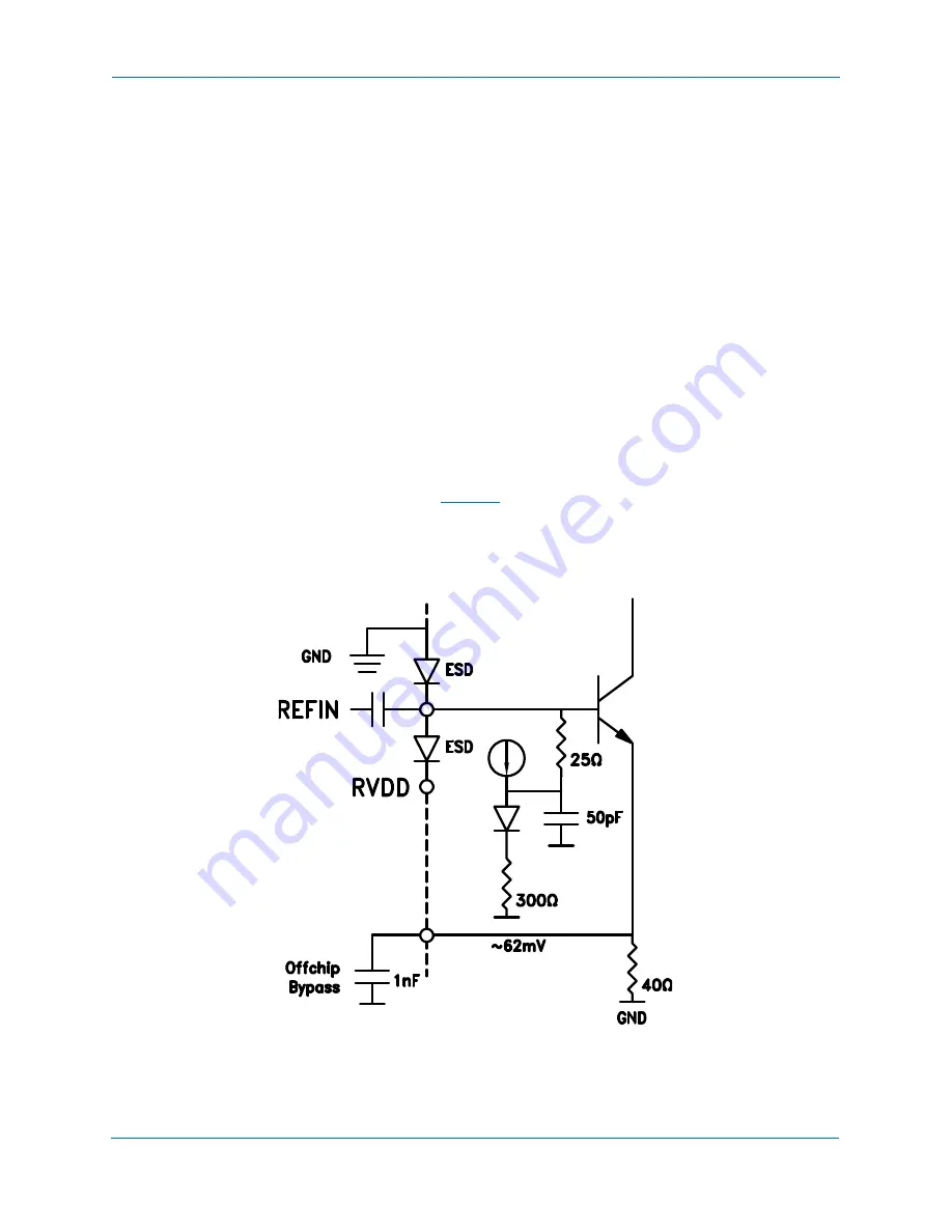
The crystal reference input stage is shown in
. This is a common-emitter single-ended bipolar
buffer. Expected input is a 0 dBm sinusoid from a 50 Ohm source. The buffer input impedance is dominated
by a 25 Ohm shunt resistor in series with a 50 pF on-chip capacitor. The reference path phase noise floor
is approximately equivalent to -159 dBc/Hz. For best performance care should be taken to provide a crystal
reference source with equivalent or better phase noise floor.
Figure 1. REFIN Input


