background image

DETAILED SPECIFICATIONS

LINE VOLTAGE

Yes/

No

Hi/Lo Line

Nom.

Unit

Notes

US 120vac/60Hz

Yes

108-132

120

Vrms

Normal Operation

Parameter

Spe

cific

atio

n

Unit

Test

Limits

Conditions

Notes

Amp Section

Type (Class AB, D,

other)

D

n/a

Class D Preferred...Sink

required for Class AB

Load Impedance

(speaker)

8

Ohms

n/a

Nominal

Z-curve required

Rated Output Power

200

Watts

120

1 input driven

Input voltage 120 VAC, 60 Hz

THD

1

%

2

22k filter

120W (Power Bandwidth

30-100Hz) @ 120 VAC

THD @ 1 Watt

0.5

%

0.5

22k filter

DC Offset

<20

mV-DC

30

@ Speaker Outputs

Damping factor

>80

DF

>50

Measured across amplifier

outputs

Input Sensitivity

Input Frequency

35

Hz

Nominal Freq.

1 input driven

Line Input

265

mVrms

±2dB

To Rated Power/

Vol @ Max

1 input driven: AP source Z =

600 ohms

Speaker/Hi Level Input

7

Vrms

±2dB

To Rated Power/

Vol @ Max

1 input driven: AP source Z =

25 ohms

Signal to Noise

SNR-A-Weighted

100

dBA

90

Relative to rated

output

A-Weighting filter

SNR-unweighted

75

dBr

70

Relative to rated

output

22k filter

SNR rel. 1W-unweighted

(22k)

65

dBr

55

relative to 1W

Output

22k filter

Residual Noise Floor

2

mVrms

3

Volume @max, using RMS reading DMM/VOM (or

A/P) , BW <20KHz

Residual Noise Floor

1.5

mVrms(max)

2

Volume @max, w/ A/P Swept Bandpass

Measurement (Line freq.+ harmonics) , BW<20Khz

Input Impedance

Line Input

10K

ohms

n/a

Nominal

Speaker/Hi Level Input

5K

ohms

n/a

Nominal

Filters

0dBr = 1w @ 50Hz

Low Pass (fixed or

variable)

Varia

ble

Low Pass filter (point or

range)

60-1

80

Hz

±2dB

-3dB Point

Slope

24

dB/Octave

n/a

Q

1

Damping

n/a

Subsonic filter (HPF)

25

Hz

±2dB

-3dB Point

Slope

12

dB/Octave

n/a

Q

1

Damping

n/a

4

Amplifier/Subwoofer

BU-150

Summary of Contents for BU-150

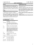
Page 1: ...Infinity Systems Inc 250 Crossways Park Drive Woodbury N Y 11797 1 800 553 3332 A Harman International Company Rev A 3 2000 BU 150 Powered Subwoofer SERVICE MANUAL...

Page 2: ...lacement C1 2 2200uF 100V electrolytic filter caps Be sure replacement part is at least the same working voltage and capacitance rating Also the lead spacing is important Incorrect spacing may cause p...

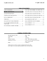
Page 3: ...LE OF CONTENTS SAFETY INFORMATION 2 GENERAL SPECIFICATIONS 3 DETAILED SPECIFICATIONS 4 CONTROLS AND THEIR FUNCTION 6 BU 150 CONNECTIONS 7 OPERATION 11 BU 150 TEST SET UP AND PROCEDURE 12 BU 150 POWER...

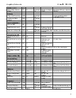
Page 4: ...ol Max 1 input driven AP source Z 600 ohms Speaker Hi Level Input 7 Vrms 2dB To Rated Power Vol Max 1 input driven AP source Z 25 ohms Signal to Noise SNR A Weighted 100 dBA 90 Relative to rated outpu...

Page 5: ...er Input w 1 ch Driven Signal Present Turn on time 1 sec Amp connected and AC on then input signal applied Auto Mute Turn OFF Time 3 min T before muting after signal is removed Power on Delay time 1 s...

Page 6: ...roll off points 4 Power On indicator 5 Phase 0 180 switch to change audio signal polarity 6 Level This controls the volume level of the subwoofer TO REDUCE THE RISK OF ELECTRIC SHOCK DO NOT EXPOSE TH...

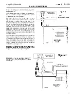
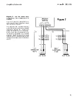
Page 7: ...one end of each stereo pair of leads to the preamplifier s left and right outputs and connect the other end to the corresponding left and right LOW LEVEL INPUTS 1 on the subwoofer If you are using a t...

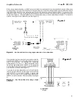
Page 8: ...woofer pair See Figure 3 Figure 3 Use this method when using single subwoofer or two subwoofers The subwoofer may be connected to your system using the HIGH LEVEL INPUTS 4 on the plate located on the...

Page 9: ...necting one subwoofer to satellites Depending on whether you are using one or two subwoofers connecting your satellites can be accomplished in one of two ways If you are using a single subwoofer with...

Page 10: ...ofer has a variable frequency control that can be used to block unwanted frequencies between 50 150Hz from being reproduced by the subwoofer When you set this control depends on the low frequency capa...

Page 11: ...This will increase low bass while leaving the mid bass sounding the same as it did before the adjustment To reduce low bass without changing midbass turn the Crossover Frequency control UP and the Vol...

Page 12: ...om port tube opening 5 Turn off generator turn VOLUME control fully counterclockwise disconnect RCA cables 6 Connect one pair of speaker cables to either high level input terminal on UUT Cables should...

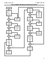
Page 13: ...k I P of module to GND 0V D C Power up with no signal I P LED RED OK OK OK OK OK OK OK OK Check C29 and Pre AMP Check O P to module for 80Vpp square wave measure to GND Check L1 L2 L3 L4 C6 C24 Check...

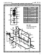
Page 14: ...PLASTIC BAG CARTON 200420 SCREWS 10 SCREWS 8 TRIM RING 200401 SCREWS 4 FOOT BASE Each 200870 FEET PART Set of 4 200310 CABINET NOT FOR SALE 15 WOOFER 200400 BU 150 CABINET ASSEMBLY BU 150 PACKING AMPL...

Page 15: ...ws to secure input jacks 5 6 70171 10 x 1 machine screw Bolts 4 7 70172 10 Keps Nut 4 8 70173 6 x 0 5 Screws for fuse PCB 2 9 80124 Transformer MCI4700 SAFETY PART 1 10 80123 250V 1 5A T type SLO BLO...

Page 16: ...1 6 Amplifier Subwoofer BU 150 BU 150 PCB Version 3 52 Component Side Trace Version 3 52 Component Side Trace Layer 5 5 4 4 3 3 2 2 1 1 A A B B C C D D E E F F G G...

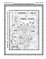
Page 17: ...1 7 Amplifier Subwoofer BU 150 Version 3 52 Solder Side Trace Layer as viewed through the board 5 5 4 4 3 3 2 2 1 1 A A B B C C D D E E F F G G BU 150 PCB Version 3 52 Solder Side Trace...

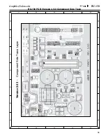
Page 18: ...1 8 Amplifier Subwoofer BU 150 BU 150 PCB Version 3 53 Component Side Trace Version 3 53 Component Side Trace Layer 5 5 4 4 3 3 2 2 1 1 A A B B C C D D E E F F G G...

Page 19: ...1 9 Amplifier Subwoofer BU 150 BU 150 PCB Version 3 53 Solder Side Trace Version 3 53 Solder Side Trace Layer as viewed through the board 5 5 4 4 3 3 2 2 1 1 A A B B C C D D E E F F G G...

Page 20: ...itors C1 30710 2200uF 100V 80 20 Electrolytic Radial 1 Safety part C2 30710 2200uF 100V 80 20 Electrolytic Radial 1 Safety part C3 30514 47nF 50V 80 20 Mono ceramic axial 1 C4 5 30504 100nF 50V 80 20...

Page 21: ...FOLLOW ONE OR MORE OF THESE STEPS MAY RESULT IN THE INSTANT DESTRUCTION OF THE MODULE WHEN POWERED UP Align white indent marker on Amp Module with indent marker on main PCB alternately observe positio...

Page 22: ...2 2 Amplifier Subwoofer BU 150 BU 150 SCHEMATIC 1 of 2 5 5 4 4 3 3 2 2 1 1 A A B B C C D D E E F F G G BU 150 Schematic 1 of 2...

Page 23: ...2 3 Amplifier Subwoofer BU 150 5 5 4 4 3 3 2 2 1 1 A A B B C C D D E E F F G G BU 150 Schematic 2 of 2 BU 150 SCHEMATIC 2 of 2...

Reviews: