Cascade Model Twelve
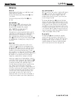
Power On
Plug your subwoofer’s AC cord into a wall outlet. Do not use the
outlets on the back of the receiver.
Initially set the Subwoofer Level (Volume) Control
§
to the
“min” position.
Turn on your sub by pressing the Power Switch
¡
on the
rear panel.
Auto On/Standby
With the Power Switch
¡
in the ON position, the Power
Indicator LED
¢
will remain backlit in red or green to
indicate the On/Standby mode of the subwoofer.
RED = STANDBY (No signal detected, Amp Off)
GREEN = ON (Signal detected, Amp On)
The subwoofer will automatically enter the Standby mode after
approximately 10 minutes when no signal is detected from your
system. The subwoofer will then power ON instantly when a
signal is detected. During periods of normal use, the Power
Switch
¡
can be left on. You may turn off the Power Switch
¡
for extended periods of nonoperation, e.g., when you are away
on vacation.
Adjust Gain
Turn on your entire audio system and start a CD or movie
soundtrack at a moderate level. Turn up the Subwoofer Level
(Volume) Control
§
about half way. If no sound emanates from
the subwoofer, check the AC-line cord and input cables. Are the
connectors on the cables making proper contact? Is the AC
plug connected to a “live” receptacle? Has the Power Switch
¡
been pressed to the “On” position? Once you have confirmed that
the subwoofer is active, proceed by playing a CD, record or
cassette. Use a selection that has ample bass information.
Set the overall volume control of the preamplifier or stereo to a
comfortable level. Adjust the Subwoofer Level (Volume) Control
§
until you obtain a pleasing blend of bass. Bass response should
not overpower the room but rather be adjusted so there is a
harmonious blend across the entire musical range. Many users
have a tendency to set the subwoofer volume too loud,
adhering to the belief that a subwoofer is there to produce lots
of bass. This is not entirely true. A subwoofer is there to enhance
bass, extending the response of the entire system so the bass
can be felt as well as heard. However, overall balance must
be maintained or the music will not sound natural. An
experienced listener will set the volume of the subwoofer so
its impact on bass response is always there but never obtrusive.
O
PERATION
Crossover Adjustments
NOTE: This control will have no effect if the Normal/LFE Selector
Switch
¶
is set to “LFE.” If you have a Dolby Digital or DTS
processor/receiver, the Crossover Frequency is set by the
processor/receiver. Consult your owner’s manual to learn how
to view or change this setting.
The Crossover Adjustment Control
∞
determines the highest
frequency at which the subwoofer reproduces sounds. If your main
speakers can comfortably reproduce some low-frequency sounds,
set this control to a lower frequency setting, between 50Hz
and 100Hz. This will concentrate the subwoofer’s efforts on the
ultradeep bass sounds required by today’s films and music. If you
are using smaller bookshelf speakers that do not extend to the
lower bass frequencies, set the Crossover Adjustment Control to
a higher setting, between 120Hz and 150Hz.
Phase Control
The Phase Switch
•
determines whether the subwoofer
speaker’s piston-like action moves in and out with the main
speakers, 0,˚ or opposite the main speakers, 180˚. Proper phase
adjustment depends on several variables such as room size,
subwoofer placement and listener position. Adjust the phase
switch to maximize bass output at the listening position.
Cascade 12 OM 9/21/05 5:03 PM Page 7
M odel T w elve
Cascade
7
Summary of Contents for CASCADE TWELVE
Page 5: ...4 Model Twelve Cascade...
Page 9: ...Model Twelve Cascade 8...
Page 11: ...BLOCK DIAGRAM Model Twelve Cascade 10...
Page 19: ...Model Twelve Cascade 18...
Page 20: ...Model Twelve Cascade 19...
Page 21: ...Model Twelve Cascade 20...
Page 22: ...Cascade...
Page 23: ...Model Twelve Cascade 22...
Page 24: ...Model Twelve Cascade 23...
Page 25: ...Model Twelve Cascade 24...
Page 26: ...Model Twelve Cascade 25...
Page 27: ...Model Twelve Cascade 26...
Page 28: ...Model Twelve Cascade 27...
Page 29: ...Model Twelve Cascade 28...
Page 30: ...Model Twelve Cascade 29...
Page 31: ...Model Twelve Cascade 30...
Page 32: ...Model Twelve Cascade 31...
Page 33: ...Model Twelve Cascade 32...


