background image

S

ET

C

ONTROLS

...

P

OWER

O

N

A

DJUST

G

AIN

C

ROSSOVER

A

DJUSTMENTS

P

HASE

C

ONTROL

...

O

PERATION

1.

Initially set the HPS’s Gain control to the “O” position.

2.

Initially set the HPS’s Crossover control to the 100Hz position.

3.

Plug your HPS’s AC cord into a wall outlet. Do not use the outlets on the back of the receiver.

4.

Turn on your HPS sub by pressing the power button on the center of the front panel.

5.

Turn on your entire audio system and start a CD or movie sound track at a moderate level.

6.

Turn your HPS’s Gain control 

(Figure 2) up to the “5” position (half way). If no sound

emanates from the subwoofer, check the AC-line cord and input cables. Are the connectors
on the cables making proper contact? Is the AC plug connected to a “live” receptacle? Has
the power button been pressed to the “on” position? (Note: A green indicator on the front
panel will light when the power is on.) Once you have confirmed that the subwoofer is
active, proceed by playing a CD, record or cassette. Use a selection that has ample bass
information.

7.

Set the overall volume control of the preamplifier or stereo to a comfortable level. Adjust
the subwoofer’s Gain control 

(Figure 2) until you obtain a pleasing blend of bass. Bass

response should not overpower the room but rather be adjusted so there is a harmonious
blend across the entire musical range. Many users have a tendency to set the subwoofer
volume too loud, adhering to the belief that a subwoofer is there to produce lots of bass.
This is not entirely true. A subwoofer is there to enhance bass, extending the response of
the entire system so the bass can be felt as well as heard. However, overall balance must
be maintained or the music will not sound natural. An experienced listener will set the
volume of the subwoofer so its impact on bass response is always there but never obtrusive.

8.

Crossover Control 

(Figure 2) – The Low-Pass control determines the highest frequency

at which the subwoofer reproduces sounds. If your main speakers can comfortably reproduce
some low-frequency sounds, set this control to a lower frequency setting, between
50Hz – 100Hz. This will concentrate the subwoofer’s efforts on the ultradeep bass sounds
required by today’s films and music. If you are using smaller bookshelf speakers that do
not extend to the lower bass frequencies, set the low-pass crossover control to a higher
setting, between 120Hz – 150Hz.

9.

The Phase Control 

(Figure 2) determines whether the subwoofer speaker’s piston-like

action moves in and out with the main speakers, 0˚, or opposite the main speakers, 180˚. 
Proper phase adjustment depends on several variables such as room size, subwoofer
placement and listener position. Adjust the phase switch to maximize bass output at the
listening position. 

10.

The EQ switch, located on the front panel, optimizes the subwoofer's performance for
both movie and music listening. When in the “Video” position, a special EQ circuit is
activated, enhancing low frequencies by approximately 3dB at 32Hz and delivering the
full impact and excitement of today’s movie soundtracks. When in the “Audio” position,
the subwoofer provides the accurate and linear frequency response that is ideal when a
natural tonal balance is desired for music listening.

11.

Remember: every system, room and listener is different. There are not necessarily any right
or wrong settings; any setting you choose will result in excellent performance. Should you
decide to fine-tune your system for optimum performance, be patient and trust your ears.
It will be worth the effort involved to fully “tweak” your system.

4

4

2

3

Summary of Contents for HPS-1000

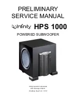
Page 1: ...PRELIMINARY SERVICE MANUAL HPS 1000 POWERED SUBWOOFER Infinity Systems Incorporated 250 Crossways Park Dr Woodbury New York 11797...

Page 2: ...CONTENTS SPECIFICATIONS 2 SET UP GUIDE 3 CONTROLS 6 OPERATION 7 PARTS LIST 9 SCHEMATICS 17...

Page 3: ...e Filters Low Pass fixed or variable Variable Note Center positon 100Hz Low Pass filter point or range 45 120 Hz 2dB Slope 12 dB Octave n a Q Damping n a Normal Direct Switch yes functional Low Pass f...

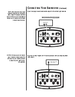
Page 4: ...CONNECTING YOUR SUBWOOFER If your receiver processor does not have subwoofer outputs for the left and right channels L L R R INPUTS OUTPUTS B LINK...

Page 5: ...confuse this with a single LFE output as described below In that case it is recommended that you use a Y connector not included to maximize performance LOW LEVEL OUT LOW LEVEL IN L R 120Hz 160Hz 80Hz...

Page 6: ...hooked up as shown below the subwoofer will limit the low frequency information that is returned to your receiver amplifier Your receiver amplifier does not need to waste valuable power reproducing t...

Page 7: ...ossover Controls the frequency below which the subwoofer will begin working 3 Phase Reverse normal switch changes audio signal polarity 4 Gain Controls subwoofer volume level 5 Input Switches between...

Page 8: ...ound natural An experienced listener will set the volume of the subwoofer so its impact on bass response is always there but never obtrusive 8 Crossover Control Figure 2 The Low Pass control determine...

Page 9: ...protection is completely automatic with no user adjustments However if you do hear distortion continuously while playing music the input signal level feeding the HPS may be too high and should be low...

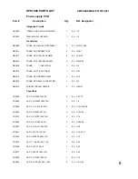
Page 10: ...9 TRANS NPN TIP29B C T0220 1 EA Q19 QB0033 TRANS NPN 250V 1A TO220 TIP47 1 EA Q3 QM0015 MOSFET IRF640 TO220AB 2 EA Q9 Q27 Capacitors CC0020 CAP CA 470PF 100V 5 2 EA C3 C73 CC0040 CAP CA 4700PF 100V 10...

Page 11: ...RES CF 10K 1 4W 5 1 EA R17 RC0037 RES CF 2K0 1 4W 5 1 EA R3 RC0082 RES CF 100K 1 2W 5 1 EA R77 RC0083 RES CF 100K 1 4W 5 2 EA R25 R51 RC0091 RES CF 150K 1 2W 5 1 EA R94 RC0116 RES CF 330K 1 4W 5 1 EA...

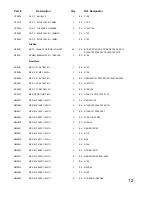
Page 12: ...10R 0 6W 1 FLAMEPROOF 2 EA R21 R93 RW0022 RES WW 0R1 2W 5 2 EA R40 R92 RX0072 RES MO 100R 1W 5 1 EA R19 RX0080 RES MO 4R7 2W 5 1 EA R20 ELEVATED 5MM RC0273 RES ZERO OHM 1 4W 1 EA L3 Miscellaneous 540...

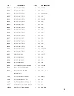
Page 13: ...N 40V 6A TO92 2N4401 1 EA Q101 QB0017 TRANS NPN 150V 0 6A 2N5551 2 EA Q1 Q5 QB0018 TRANS PNP 150V 0 6A 2N5401 2 EA Q2 Q6 QB0049 TRANS TO92 2N3819 1 EA Q102 MUST BE SELECTED QM0015 MOSFET IRF640 TO220A...

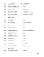
Page 14: ...K0 1 4W 5 2 EA R127 R131 RC0083 RES CF 100K 1 4W 5 2 EA R16 R128 RC0273 RES ZERO OHM 1 4W 5 EA R32 R113 R119 C126 D110 RM0001 RES MF 1K00 1 4W 1 3 EA R2 R34 R120 RM0002 RES MF 10K0 1 4W 1 5 EA R125 R1...

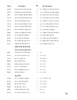
Page 15: ...RES MF 7K87 1 4W 1 1 EA R37 RM0307 RES MF 1K15 1 4W 1 1 EA R109 RM0352 RES MF 2K05 1 4W 1 1 EA Z100 RM0363 RES MF 24K3 1 4W 1 2 EA R115 R117 RM0366 RES MF 3K24 1 4W 1 1 EA R108 RX0074 RES MO 4K7 1W 5...

Page 16: ...BRIDGE 1 EA USED ON THE BRIDGE CE0004 CAP E 2 2UF 450V 20 85C 1 EA C2 CF0057 CAP FX 22UF 250V 10 1 EA C1 DB0006 RECT 8A 400V BRIDGE 1 EA D1 HN0006 NUT KEP 1 4AF 6 32 ZNP 1 EA USED ON THE BRIDGE HEATSI...

Page 17: ...KNOB FOR HPS SERIES 2 EA KNOBS FOR THE POTS RP0077 POT KNOB FOR HPS SWITCH 3 EA KNOB FOR THE PUSH SWITCH RP0078 POT KNOB FOR HPS BUTTON 1 EA KNOB FOR THE POWER BUTTON TS0017 FIBREGLASS HT210 2AWG 3 1...

Page 18: ...HE IEC CONNECTOR HS0065 SCREW 6 32X1 4 PAN PHIL BLK 1 EA USED ON MM0025 HS0072 SCREW 4 HI LOW PAN PHIL ZNP 4 EA TO SECURE THE CUPS AND CABLE TIES HS0074 SCREW 4 40X3 4 PAN PHIL ZNP 2 EA BETWEEN SHIELD...

Page 19: ......

Page 20: ......

Page 21: ......

Page 22: ......

Page 23: ......

Page 24: ......

Page 25: ......

Page 26: ......

Reviews: