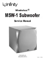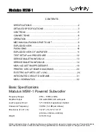
Infinity Systems Inc. 250 Crossways Park Dr. Woodbury, New York 11797 (516) 496-3400
2
3.
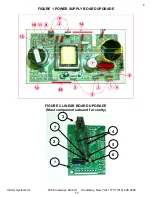
D1 should be MUR1540 MOTOROLA ONLY, if not replace with DR0091, RECT, 15A 200V
MUR1540 MOTOROLA
4.
Add a thin ceramic, CERAMIC PLATE TO-220, INSULATOR 0.025 THICK " (MS0017) behind Q1
with thermal grease on both sides of the ceramic.
Ensure that grease covers the complete surface of ceramic on both sides.
5.
Remove SILPAD (MS0005 SILPAD, .009" .3C/W TO3P) behind D3 and thoroughly clean the
adhesive film with an Alcohol blended cleaner such as IPA etc.
6.
Parts Q4, Q5, D1, D3 must also have thermal grease between the devices and the heatsink.
7.
Verify that C6 is a 106 deg.C part, if not replace with CAP, E 1000uF 100V 105C (CE0145)
8.
Ensure that C11 is 0.0047uF (4700PF 100V 10%). This part must be axial and not a radial part.
If not order Infinity Part# CC0040
9.
Ensure that R1, R2 are 0.1 ohm resistors (Color Code - Brown, Black, Silver and Gold) RES, MO
0.1 ohm 2W 5% Metal film, not wire wound. If not order Infinity Part# RX0109
10.
Ensure that Q6 is MPS A92 PNP TO92 MPSA92TR. If not order Infinity Part # QB0014
11.
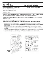
Ensure that R22 is 100K, 1/2 watt part. (Color Code - Brown, Black, Yellow and Gold), RES, CF
100K 1/2W 5%. If not order Infinity Part# 293-100k
12.
Ensure that R26 is SURGISTOR 10R 2A CL-110 (13S100L) If not order Infinity Part# KS0020
13.
Ensure that R30 is 160K part (Color Code - Brown, Blue, Yellow, Gold), RES, CF 160K 1/4W 5%.
If not order Infinity Part# RC0136
14.
Assemble the (new part) PRIMARY BLACK HEATSINK 810158 on the (2) FET(Q4 & Q5) side.
ENSURE THAT THE FETS ARE FLUSH AGAINST THE HEATSINK.
15.
Assemble the 810157, HTSNK, FET SEC BLACK heat sink on side of three devices (Q1, D1, &
D3) Install FET CLIP 810056 on Q1 (not shown in illustration)
2) LINEAR BOARD UPGRADE
Step
OPERATION
Remove Linear Board from Amplifier Assembly
A
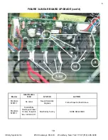
Remove SILPADS under indicated location “A” in Figure 3 and thoroughly clean
surface with IPA or equivalent.
STEPS CORRESPOND WITH FIGURE 2
1.
Replace R43 with Infinity Part# RM0002, RES, MF 10K0 1/4W 1%
2.
Locate, unsolder and lift a lead from C1 (CAP, E 2.2UF 50V BP 6X11 5MMLS) that is
closest to the trim pot, see image.
3.
Mount new Thermistor (KS0026) at linear board mounting point as shown by removing
the screw retaining the PCB bracket, inserting the Thermistor and rethreading the
screw to hold down both the PCB and Thermistor, the tab “sandwiched” between the
bracket and faceplate. Thermistor body should be flush with the faceplate.
4.
Important ! Cover both exposed thermistor leads with Shrink tubing (TS0009)
5.
Solder RC0273 (RES, ZERO OHM 1/4W) to one lead of new Thermistor, as depicted.
6.
Solder other lead of RC0273 to PCB location previously occupied by C1, as depicted.
7.
Solder lifted lead of C1 to Thermistor as depicted.
STEPS CORRESPOND WITH FIGURE 3
8.
Insert (new part) MS0005, SILPAD, .009" .3C/W TO3P between Heatsink (810156) and
both Regulators U2 and U3
9.
Add (new part) HEATSINK, LINEAR VOLTAGE REG (810156):
B.
Apply thermal grease to both surfaces of all (4) of the CERAMIC PLATE TO-220,
CERAMIC INSULATOR 0.025” (MS0017), and sandwich between each power device
and the faceplate. Replace the screws and clips; tighten.
10.
Secure Voltage regulators U2 and U3 to 810156, HEATSINK, LINEAR VOLTAGE REG
using 810066, HEATSINK-FET CLIPS. These clip on and do not use screws
11.
Secure THERMISTOR leads & C1 using RTV DOW CORNING 747 or equivalent as
depicted
15
Summary of Contents for Modulus MSW-1
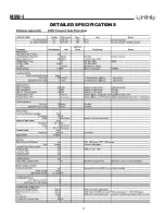
Page 3: ...MSW 1 3 DETAILED SPECIFICATIONS ...
Page 4: ...MSW 1 4 DETAILED SPECIFICATIONS Cont ...
Page 5: ...MSW 1 5 CONTROLS ...
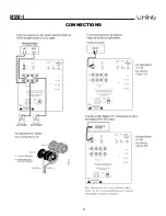
Page 6: ...MSW 1 6 CONNECTIONS ...
Page 10: ...MSW 1 10 PACKAGING 16 17 18 19 21 20 22 00533 24 23 ...
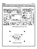
Page 20: ...MSW 1 20 300W HC BASH Power Supply 230V 120V Volume Right Board ...
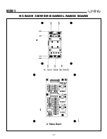
Page 21: ...MSW 1 21 HC BASH 300W EM BOARD IL RABOS BOARD ...
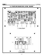
Page 22: ...MSW 1 22 IL FEATURE BOARD HI LEVEL BOARD ...
Page 23: ...HC BASH 300W LINEAR BOARD MSW 1 23 ...
Page 32: ...MSW 1 32 LINEAR PCB ...
Page 33: ...MSW 1 33 VOLUME LC HI LEVEL OPTIONAL BALANCE 250W AC DC and EMI ...
Page 34: ...MSW 1 34 FEATURE MAIN BOARD ...
Page 35: ...MSW 1 35 FEATURE HOUSEKEEPING ...
Page 36: ...MSW 1 36 FEATURE RABOS ...
Page 37: ...MSW 1 37 POWER SUPPLY ...

