background image

MSW-1

26

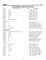
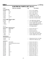
ELECTRICAL PARTS LIST (Cont.)

Part#

Reference Designator

Qty

Description

RESISTORS
RC0273

R19,R20,R35,R36

4

RES, ZERO OHM 1/4W

RM0001

R12,R13,R14,R15,R28,R29,R30,R31

8

RES, MF 1K00 1/4W 1%

RM0002

R1,R2,R5,R6,R22,R38,R41,R42

8

RES, MF 10K0 1/4W 1%

RM0021

R7,R8,R23,R24

4

RES, MF 1K82 1/4W 1%

RM0024

R17,R18,R33,R34

4

RES, MF 2K21 1/4W 1%

RM0027

R21,R37

2

RES, MF 33K2 1/4W 1%

RM0029

R9,R10,R25,R26

4

RES, MF 3K01 1/4W 1%

RM0144

R43

1

RES, MF 47K5 1/4W 1%

RM0180

R16,R32

2

RES, MF 4K99 1/4W 1%

RP0059

R11,R27

2

POT, 2K 8MM TOP ADJ/COVER

RX0048

R39,R40

2

RES, MO 330R 1W 5%

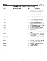
Miscellaneous
JH0016

J7

1

CNCTR, HEADER 2PIN .100CTR

JH0074

J13,J14

2

CNCTR, HEADER 8PIN LOCKING .1C

MM0025

J9,J10

2

MISC, PC MT SCREW TERM 6-32

MT0003

J1

1

TERM, FASTON MALE PCMT 250X032

MT0023

J3,J6

2

TERM, FASTON MALE PCMT 187X032

MT0036

J2

1

TERM, FASTON MALE PCMT 205X032

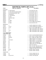
PCB, POWER SUPPLY
SEMICONDUCTORS

DR0086

D6,D7

2

RECT, 1A 600V ULTRAFAST MUR160

DS0001

D2,D10

2

RECT, 100mA 75V SIGNAL 1N4148T

DS0002

D5,D8,D9

3

RECT, 100MA 200V SIGNAL 1N3070

DZ0004

Z1

1

ZENER, 500mW 18V 5% 1N5248B

DZ0021

Z2,Z3,Z4,Z5

4

ZENER, 500MW 15V 5% 1N5245B

QB0002

Q2

1

TRANS, NPN 40V .6A TO92 2N4401

QB0014

Q6

1

TRANS, PNP TO92 MPSA92TR

QB0017

Q3

1

TRANS, NPN 150V 0.6A 2N5551TR

DD0003

D4

1

RECT, 1A2 60V DIAC

DR0026

D3

1

RECT, 16A 200V CATHODE FEP16DT

DR0087

D1

1

RECT, 15A 200V ULTRA MUR1540

HC1011

U1

1

HYBRID, THK FILM HC BUCK CNTR

QM0004

Q4,Q5

2

MOSFET, IRF740 TO220AB

QM0020

Q1

1

MOSFET, IRF540 TO220AB

CAPACITORS
CC0025

C2

1

CAP, CA 1000PF 100V 10%

CC0040

C11

1

CAP, CA 4700PF 100V 10%

CC0059

C3,C4,C5,C18

4

CAP, CA .1UF 100V 20%

Summary of Contents for Modulus MSW-1

Page 1: ...Modulus MSW 1 Subwoofer Service Manual Infinity Systems Inc 250 Crossways Park Dr Woodbury New York 11797 REV 5 11 2002 ...

Page 2: ...TED CIRCUIT DIAGRAMS 31 MSW 1 SCHEMATICS 32 Basic Specifications Modulus MSW 1 Powered Subwoofer Frequency Range 27Hz 100Hz 3dB Amplifier Output 300 watts RMS 600 watts peak Low Frequency Driver 12 C M M D magnetically shielded Crossover Frequency 100 Hz 12 dB per octave Dimensions H x W x D 16 1 2 x 14 1 2 x 19 1 4 419mm x 368mm x 489mm Weight 42 lb 19 1kg Infinity continually strives to update a...

Page 3: ...MSW 1 3 DETAILED SPECIFICATIONS ...

Page 4: ...MSW 1 4 DETAILED SPECIFICATIONS Cont ...

Page 5: ...MSW 1 5 CONTROLS ...

Page 6: ...MSW 1 6 CONNECTIONS ...

Page 7: ...selection that has ample bass information Set the overall volume control of the preamplifier or stereo to a comfortable level Adjust the subwoofer s Gain Control 8 until you obtain a pleasing blend of bass Bass response should not overpower the room but rather be adjusted so there is a harmonious blend across the entire musical range Many users have a tendency to set the subwoofer volume too loud ...

Page 8: ...80 002 Platinum 336880 001 8 SCREW 8 905401 006 8 x 75 PB PPH BLK 9 PORT TUBE 336804 001 10 SCREW 4 903101 016 8 x 1 PB TRPH BLK 11 FOOT PAD 4 334192 001 12 FOOT 4 Charcoal 334186 004 Platinum 334186 003 13 AMPLIFIER ASSEMBLY Not for Sale 14 SCREW 10 905401 006 8 x 75 PB PPH BLK 15 GRILLE Charcoal 336770 002 Platinum 336770 001 PACKAGING 16 SYSTEM 4 1 MODULUS SAT CTR 17 OWNER S MANUAL 336782 001 1...

Page 9: ...ation above this can be accomplished by carefully pulling them out of the cavities with long nosed pliers or similar tool 3 Remove the 6 Phillips screws that are now exposed 4 Remove the front baffle 5 Remove the 8 screws that secure the driver 6 To service the amplifier remove the 10 Phillips screws at the rear of the enclosure and pull the amplifier out of the back 15 ...

Page 10: ...MSW 1 10 PACKAGING 16 17 18 19 21 20 22 00533 24 23 ...

Page 11: ...WS TO SEPARATE REAR COVER FROM AMP PLATE 00537 AC SOCKET JC0129 FUSE HOLDER FH0012 FUSE 3A 1 25 x 25 FS0022 POWER SWITCH SR0032 AMP COVER 930050 00532 High Level Binding Posts JC0070 set of 8 cluster Dual RCA jacks JC0049 Switch SPDT TOGGLE 4 SR0007 ...

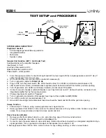
Page 12: ...e 0 disconnect RCA cable 7 Connect one pair of speaker cables to Speaker Level input terminal on UUT Cables should be connected to an integrated amplifier fed by the signal generator 8 Change Input selector switch to Speaker 9 Turn on generator and adjust so that speaker level input at the amplifier is 2 2V 30 Hz 10 Turn LEVEL control full counterclockwise 10 11 Green LED should light immediate ba...

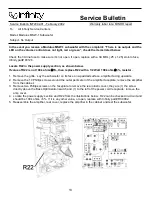
Page 13: ...eplace R22 with a 1 2 Watt 100k ohm 5 resistor 1 Remove the grille Lay the subwoofer on its face on a padded surface amplifier facing upwards 2 Remove the 10 Phillips screws around the outer perimeter of the amplifier faceplate remove the amplifier from the cabinet 3 Remove two Phillips screws on the faceplate to remove the rear plastic cover they are 1 the screw directly above the Bass Optimizati...

Page 14: ...T CLIP CLIP ON NO SCREW 2 Used with heatsink 810156 on U2 U3 810156 HEATSINK LINEAR VOLTAGE REG 1 810157 HEATSINK FET SEC BLACK 1 Replaces 810091 810158 HEATSINK FET PRIMARY BLACK 1 Replaces 810092 810056 HEATSINK FET CLIP 9 x 5 x 2 1 Use with Q1 MS0017 MISC CERAMIC PLATE TO 220 CERAMIC INSULATOR 0 025 5 Use with Q1 3 4 7 8 Thermal grease A R Use with Q1 3 4 5 7 8 D1 D3 RM0002 R43 RES MF 10K0 1 4W...

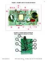
Page 15: ...mble the 810157 HTSNK FET SEC BLACK heat sink on side of three devices Q1 D1 D3 Install FET CLIP 810056 on Q1 not shown in illustration 2 LINEAR BOARD UPGRADE Step OPERATION Remove Linear Board from Amplifier Assembly A Remove SILPADS under indicated location A in Figure 3 and thoroughly clean surface with IPA or equivalent STEPS CORRESPOND WITH FIGURE 2 1 Replace R43 with Infinity Part RM0002 RES...

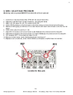
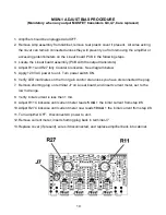
Page 16: ...rol dial unless you have disconnected the plug 5 Remove shorting plug on terminal J7 on Linear board and insert current meter set to the low mA range 6 Verify initial current is less then 1 mA 7 Adjust R11 Clockwise until current meter reads 5 mA plus the initial current from step 6 8 Adjust R27 Clockwise until current meter now reads 10 mA plus the initial current from step 6 9 Turn amplifier OFF...

Page 17: ...Infinity Systems Inc 250 Crossways Park Dr Woodbury New York 11797 516 496 3400 4 FIGURE 1 POWER SUPPLY BOARD UPGRADE FIGURE 2 LINEAR BOARD UPGRADE Most components absent for clarity 5 2 3 1 4 5 6 7 17 ...

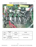
Page 18: ... FIGURE 3 LINEAR BOARD UPGRADE cont d Model Identification 120V STATUS ACTION Modulus MSW 1 No Label Needs Reliability Upgrade Follow Steps Outlined Above Modulus MSW 1 Small White Rectangular label On Amp faceplate Rev II 2002 XXX Modified by factory NONE REQUIRED 8 9 10 A B 11 18 ...

Page 19: ...ise See diagram below 5 Apply 120 VAC power to unit Turn power switch ON 6 Verify LED illuminates on the front gain control dial unless you have disconnected the plug 7 Remove shorting plug on terminal J7 on Linear board and insert current meter set to the low mA range 8 Verify initial current is less then 1 mA 9 Adjust R11 Clockwise until current meter reads 5 mA the initial current from step 8 1...

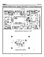
Page 20: ...MSW 1 20 300W HC BASH Power Supply 230V 120V Volume Right Board ...

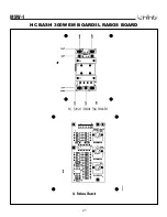
Page 21: ...MSW 1 21 HC BASH 300W EM BOARD IL RABOS BOARD ...

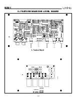
Page 22: ...MSW 1 22 IL FEATURE BOARD HI LEVEL BOARD ...

Page 23: ...HC BASH 300W LINEAR BOARD MSW 1 23 ...

Page 24: ...E0103 C102 1 CAP E 100UF 35V 85DEG 5MMLS CE0108 C3 C5 2 CAP E 4 7UF 16V BIPOLAR 5X11 CF0104 C12 C13 2 CAP F 1UF 63V 5 5MMLS CF0125 C6 C8 2 CAP F 068UF 100V 5 5MMLS CF0128 C7 C9 2 CAP F 033UF 100V 5 5MMLS RESISTORS RC0001 R211 1 RES CF 1K0 1 2W 5 RC0273 R1 R4 R20 R24 4 RES ZERO OHM 1 4W RC0290 R206 1 RES CF 9M1 1 4W 5 RM0001 R33 1 RES MF 1K00 1 4W 1 RM0002 R12 R13 R37 R38 R39 R100 R101 R102 R208 R2...

Page 25: ...PCB LINEAR BD SEMICONDUCTORS DS0001 D1 D2 D3 D4 D5 D6 D7 D8 D9 D10 D11 11 RECT 100mA 75V SIGNAL 1N4148T QB0017 Q2 Q6 2 TRANS NPN 150V 0 6A 2N5551TR QB0018 Q1 Q5 2 TRANS PNP 150V 0 6A 2N5401TR QM0034 Q4 Q8 2 MOSFET IRF9540 TO220AB QM0036 Q3 Q7 2 MOSFET IRF530 TO220 QM0054 Q9 1 JFET N CH J113 TO92 UA0009 U1 1 OPAMP QUAD 14P DIL TL074 084 UV0010 U2 1 VREG 15V 500MA LM7815CT UV0011 U3 1 VREG 15V 500MA...

Page 26: ...SC PC MT SCREW TERM 6 32 MT0003 J1 1 TERM FASTON MALE PCMT 250X032 MT0023 J3 J6 2 TERM FASTON MALE PCMT 187X032 MT0036 J2 1 TERM FASTON MALE PCMT 205X032 PCB POWER SUPPLY SEMICONDUCTORS DR0086 D6 D7 2 RECT 1A 600V ULTRAFAST MUR160 DS0001 D2 D10 2 RECT 100mA 75V SIGNAL 1N4148T DS0002 D5 D8 D9 3 RECT 100MA 200V SIGNAL 1N3070 DZ0004 Z1 1 ZENER 500mW 18V 5 1N5248B DZ0021 Z2 Z3 Z4 Z5 4 ZENER 500MW 15V ...

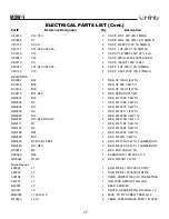
Page 27: ...4W 1 RM0002 R8 1 RES MF 10K0 1 4W 1 RM0035 R11 1 RES MF 4K75 1 4W 1 RM0039 R6 1 RES MF 5K11 1 4W 1 RM0065 R12 1 RES MF 200R 1 4W 1 RM0075 R15 R16 R18 R19 4 RES MF 475R 1 4W 1 RM0111 R7 1 RES MF 17K8 1 4W 1 RM0123 R5 1 RES MF 36K5 1 4W 1 RM0198 R24 1 RES MF 205K 1 4W 1 RM0260 R10 1 RES MF 1M0 1 4W 1 RM0339 R3 R13 R25 R34 4 RES MF 10R 0 6W 1 FLAMEPROOF RM0340 R17 R20 2 RES MF 22R 0 6W 1 FLAMEPROOF R...

Page 28: ...UT HI LEVEL BAL OPT RM0011 R5 R6 R7 R8 4 RES MF 100K 1 4W 1 RX0001 R3 R4 2 RES MO 1K 1W 5 RX0098 R1 R2 2 RES MO 510R 2W 5 CE0137 C1 C2 2 CAP E 470UF 100V BP 18X42 JC0070 J1 1 CNCTR 8PIN SPKR JACK RTANG JH0028 J3 1 CNCTR HEADER 3PIN 100CTR RABOS Board SEMICONDUCTORS UA0009 U1 1 OPAMP QUAD 14P DIL TL074 084 UA0010 U2 1 OPAMP DUAL 8PIN DIL TL082 RESISTORS RM0001 R24 R25 R33 3 RES MF 1K00 1 4W 1 RM000...

Page 29: ...F 18UF 50V 5 5MMLS Miscellaneous JH0074 J1 1 CNCTR HEADER 8PIN LOCKING 1C MISCELLANEOUS 480121 1 SUB 16B 30 205X032 205X032 SPEAKER WIRE 480122 1 SUB 16R 30 250X032 250X032 SPEAKER WIRE 810056 7 MET HTSNK CLIP 9X 5X 2 FET 3PER USED ON D1 D3 Q1 ON MAIN BOARD 4PER USED ON Q3 Q4 Q7 Q8 ON LINEAR BOARD 810066 2 MET HTSNK CLIP HPS SERIES USED Q4 Q5 ON MAIN BOARD 810091 1 MET HTSNK SEC 3FET RP5 USED ON 6...

Page 30: ...7 JC0093 1 CNCTR FEM FEM HARNESS 3P 7 5 USED WITH FEATURE AND HI LEVEL BOARD JC0111 1 CNCTR 8PIN RIBBON CABLE 3 USED ON THE RABOS ASSEMBLY JC0129 1 CNCTR AC IEC SOCKET 250 2PIN JC0169C 1 CNCTR FEM FEM HARNESS 4PS 28 USED ON J9 MM0069 3 MISC RUBBER GROMMET FREQ LEVEL WIDTH ON FRONT PANEL MS0005 7 SILPAD 009 3C W TO3P 3PER USED ON MAI BOARD 4PER USED ON THE LINEAR BOARD MSW 1 PANEL 1 MODULUS MSW 1 P...

Page 31: ...OSFET IRF9540 IRF530 IRF540 IRF740 Q1 Q4 Q5 Q3 Q7 Q4 Q8 1 G 2 D 3 S 1 1 INPUT 2 GROUND 3 OUTPUT 2 3 15V LM7815CT REGULATOR U2 1 2 1 GROUND 2 INPUT 3 OUTPUT 3 15V LM7915CT REGULATOR U3 JFET J111 J113 Q5 Q9 1 D 2 S 3 G TRANS NPN 150V 0 6A 2N5551TR MPSA92TR Q2 Q6 Q6 TRANS PNP 150V 0 6A 2N5401TR 2N4401 Q1 Q5 Q3 00540 U1 HYBRID IC ...

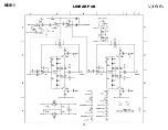
Page 32: ...MSW 1 32 LINEAR PCB ...

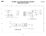
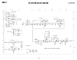
Page 33: ...MSW 1 33 VOLUME LC HI LEVEL OPTIONAL BALANCE 250W AC DC and EMI ...

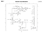
Page 34: ...MSW 1 34 FEATURE MAIN BOARD ...

Page 35: ...MSW 1 35 FEATURE HOUSEKEEPING ...

Page 36: ...MSW 1 36 FEATURE RABOS ...

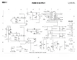
Page 37: ...MSW 1 37 POWER SUPPLY ...

Reviews: