background image

MSW-1

9

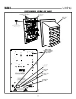
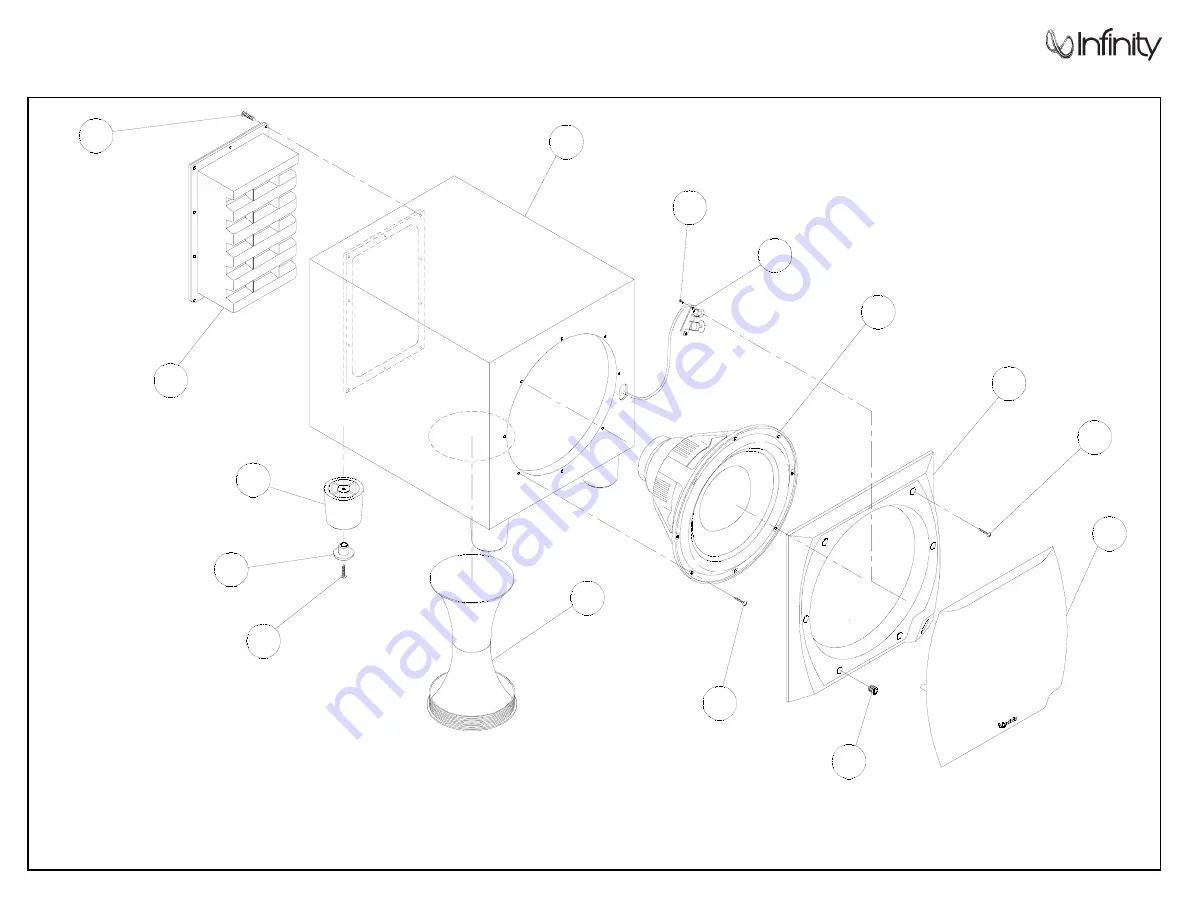
EXPLODED VIEW

1

2

3

4

5

6

7

8

9

10

11

12

13

14

00

53

1

TO SERVICE THE MSW-1 SUBWOOFER

1) Remove the grille.

2) Extract (6) rubber grille retainers as shown in the illustration above, this can be             
accomplished by carefully pulling them out of the cavities with long-nosed pliers or         
similar tool.
3) Remove the (6) Phillips screws that are now exposed.
4) Remove the front baffle.
5) Remove the (8) screws that secure the driver.
6) To service the amplifier, remove the (10) Phillips  screws at the rear of the enclosure,     
and pull the amplifier out of the back.

15

Summary of Contents for Modulus MSW-1

Page 1: ...Modulus MSW 1 Subwoofer Service Manual Infinity Systems Inc 250 Crossways Park Dr Woodbury New York 11797 REV 5 11 2002 ...

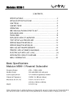
Page 2: ...TED CIRCUIT DIAGRAMS 31 MSW 1 SCHEMATICS 32 Basic Specifications Modulus MSW 1 Powered Subwoofer Frequency Range 27Hz 100Hz 3dB Amplifier Output 300 watts RMS 600 watts peak Low Frequency Driver 12 C M M D magnetically shielded Crossover Frequency 100 Hz 12 dB per octave Dimensions H x W x D 16 1 2 x 14 1 2 x 19 1 4 419mm x 368mm x 489mm Weight 42 lb 19 1kg Infinity continually strives to update a...

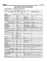
Page 3: ...MSW 1 3 DETAILED SPECIFICATIONS ...

Page 4: ...MSW 1 4 DETAILED SPECIFICATIONS Cont ...

Page 5: ...MSW 1 5 CONTROLS ...

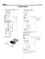
Page 6: ...MSW 1 6 CONNECTIONS ...

Page 7: ...selection that has ample bass information Set the overall volume control of the preamplifier or stereo to a comfortable level Adjust the subwoofer s Gain Control 8 until you obtain a pleasing blend of bass Bass response should not overpower the room but rather be adjusted so there is a harmonious blend across the entire musical range Many users have a tendency to set the subwoofer volume too loud ...

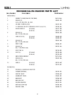
Page 8: ...80 002 Platinum 336880 001 8 SCREW 8 905401 006 8 x 75 PB PPH BLK 9 PORT TUBE 336804 001 10 SCREW 4 903101 016 8 x 1 PB TRPH BLK 11 FOOT PAD 4 334192 001 12 FOOT 4 Charcoal 334186 004 Platinum 334186 003 13 AMPLIFIER ASSEMBLY Not for Sale 14 SCREW 10 905401 006 8 x 75 PB PPH BLK 15 GRILLE Charcoal 336770 002 Platinum 336770 001 PACKAGING 16 SYSTEM 4 1 MODULUS SAT CTR 17 OWNER S MANUAL 336782 001 1...

Page 9: ...ation above this can be accomplished by carefully pulling them out of the cavities with long nosed pliers or similar tool 3 Remove the 6 Phillips screws that are now exposed 4 Remove the front baffle 5 Remove the 8 screws that secure the driver 6 To service the amplifier remove the 10 Phillips screws at the rear of the enclosure and pull the amplifier out of the back 15 ...

Page 10: ...MSW 1 10 PACKAGING 16 17 18 19 21 20 22 00533 24 23 ...

Page 11: ...WS TO SEPARATE REAR COVER FROM AMP PLATE 00537 AC SOCKET JC0129 FUSE HOLDER FH0012 FUSE 3A 1 25 x 25 FS0022 POWER SWITCH SR0032 AMP COVER 930050 00532 High Level Binding Posts JC0070 set of 8 cluster Dual RCA jacks JC0049 Switch SPDT TOGGLE 4 SR0007 ...

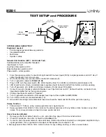
Page 12: ...e 0 disconnect RCA cable 7 Connect one pair of speaker cables to Speaker Level input terminal on UUT Cables should be connected to an integrated amplifier fed by the signal generator 8 Change Input selector switch to Speaker 9 Turn on generator and adjust so that speaker level input at the amplifier is 2 2V 30 Hz 10 Turn LEVEL control full counterclockwise 10 11 Green LED should light immediate ba...

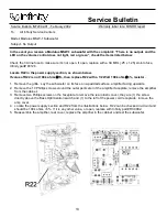
Page 13: ...eplace R22 with a 1 2 Watt 100k ohm 5 resistor 1 Remove the grille Lay the subwoofer on its face on a padded surface amplifier facing upwards 2 Remove the 10 Phillips screws around the outer perimeter of the amplifier faceplate remove the amplifier from the cabinet 3 Remove two Phillips screws on the faceplate to remove the rear plastic cover they are 1 the screw directly above the Bass Optimizati...

Page 14: ...T CLIP CLIP ON NO SCREW 2 Used with heatsink 810156 on U2 U3 810156 HEATSINK LINEAR VOLTAGE REG 1 810157 HEATSINK FET SEC BLACK 1 Replaces 810091 810158 HEATSINK FET PRIMARY BLACK 1 Replaces 810092 810056 HEATSINK FET CLIP 9 x 5 x 2 1 Use with Q1 MS0017 MISC CERAMIC PLATE TO 220 CERAMIC INSULATOR 0 025 5 Use with Q1 3 4 7 8 Thermal grease A R Use with Q1 3 4 5 7 8 D1 D3 RM0002 R43 RES MF 10K0 1 4W...

Page 15: ...mble the 810157 HTSNK FET SEC BLACK heat sink on side of three devices Q1 D1 D3 Install FET CLIP 810056 on Q1 not shown in illustration 2 LINEAR BOARD UPGRADE Step OPERATION Remove Linear Board from Amplifier Assembly A Remove SILPADS under indicated location A in Figure 3 and thoroughly clean surface with IPA or equivalent STEPS CORRESPOND WITH FIGURE 2 1 Replace R43 with Infinity Part RM0002 RES...

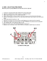
Page 16: ...rol dial unless you have disconnected the plug 5 Remove shorting plug on terminal J7 on Linear board and insert current meter set to the low mA range 6 Verify initial current is less then 1 mA 7 Adjust R11 Clockwise until current meter reads 5 mA plus the initial current from step 6 8 Adjust R27 Clockwise until current meter now reads 10 mA plus the initial current from step 6 9 Turn amplifier OFF...

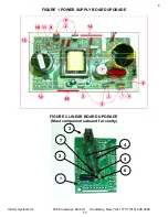
Page 17: ...Infinity Systems Inc 250 Crossways Park Dr Woodbury New York 11797 516 496 3400 4 FIGURE 1 POWER SUPPLY BOARD UPGRADE FIGURE 2 LINEAR BOARD UPGRADE Most components absent for clarity 5 2 3 1 4 5 6 7 17 ...

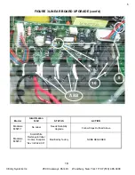
Page 18: ... FIGURE 3 LINEAR BOARD UPGRADE cont d Model Identification 120V STATUS ACTION Modulus MSW 1 No Label Needs Reliability Upgrade Follow Steps Outlined Above Modulus MSW 1 Small White Rectangular label On Amp faceplate Rev II 2002 XXX Modified by factory NONE REQUIRED 8 9 10 A B 11 18 ...

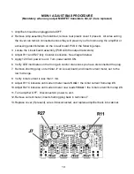
Page 19: ...ise See diagram below 5 Apply 120 VAC power to unit Turn power switch ON 6 Verify LED illuminates on the front gain control dial unless you have disconnected the plug 7 Remove shorting plug on terminal J7 on Linear board and insert current meter set to the low mA range 8 Verify initial current is less then 1 mA 9 Adjust R11 Clockwise until current meter reads 5 mA the initial current from step 8 1...

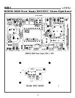
Page 20: ...MSW 1 20 300W HC BASH Power Supply 230V 120V Volume Right Board ...

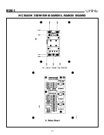
Page 21: ...MSW 1 21 HC BASH 300W EM BOARD IL RABOS BOARD ...

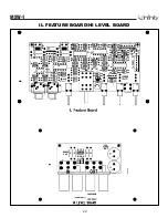
Page 22: ...MSW 1 22 IL FEATURE BOARD HI LEVEL BOARD ...

Page 23: ...HC BASH 300W LINEAR BOARD MSW 1 23 ...

Page 24: ...E0103 C102 1 CAP E 100UF 35V 85DEG 5MMLS CE0108 C3 C5 2 CAP E 4 7UF 16V BIPOLAR 5X11 CF0104 C12 C13 2 CAP F 1UF 63V 5 5MMLS CF0125 C6 C8 2 CAP F 068UF 100V 5 5MMLS CF0128 C7 C9 2 CAP F 033UF 100V 5 5MMLS RESISTORS RC0001 R211 1 RES CF 1K0 1 2W 5 RC0273 R1 R4 R20 R24 4 RES ZERO OHM 1 4W RC0290 R206 1 RES CF 9M1 1 4W 5 RM0001 R33 1 RES MF 1K00 1 4W 1 RM0002 R12 R13 R37 R38 R39 R100 R101 R102 R208 R2...

Page 25: ...PCB LINEAR BD SEMICONDUCTORS DS0001 D1 D2 D3 D4 D5 D6 D7 D8 D9 D10 D11 11 RECT 100mA 75V SIGNAL 1N4148T QB0017 Q2 Q6 2 TRANS NPN 150V 0 6A 2N5551TR QB0018 Q1 Q5 2 TRANS PNP 150V 0 6A 2N5401TR QM0034 Q4 Q8 2 MOSFET IRF9540 TO220AB QM0036 Q3 Q7 2 MOSFET IRF530 TO220 QM0054 Q9 1 JFET N CH J113 TO92 UA0009 U1 1 OPAMP QUAD 14P DIL TL074 084 UV0010 U2 1 VREG 15V 500MA LM7815CT UV0011 U3 1 VREG 15V 500MA...

Page 26: ...SC PC MT SCREW TERM 6 32 MT0003 J1 1 TERM FASTON MALE PCMT 250X032 MT0023 J3 J6 2 TERM FASTON MALE PCMT 187X032 MT0036 J2 1 TERM FASTON MALE PCMT 205X032 PCB POWER SUPPLY SEMICONDUCTORS DR0086 D6 D7 2 RECT 1A 600V ULTRAFAST MUR160 DS0001 D2 D10 2 RECT 100mA 75V SIGNAL 1N4148T DS0002 D5 D8 D9 3 RECT 100MA 200V SIGNAL 1N3070 DZ0004 Z1 1 ZENER 500mW 18V 5 1N5248B DZ0021 Z2 Z3 Z4 Z5 4 ZENER 500MW 15V ...

Page 27: ...4W 1 RM0002 R8 1 RES MF 10K0 1 4W 1 RM0035 R11 1 RES MF 4K75 1 4W 1 RM0039 R6 1 RES MF 5K11 1 4W 1 RM0065 R12 1 RES MF 200R 1 4W 1 RM0075 R15 R16 R18 R19 4 RES MF 475R 1 4W 1 RM0111 R7 1 RES MF 17K8 1 4W 1 RM0123 R5 1 RES MF 36K5 1 4W 1 RM0198 R24 1 RES MF 205K 1 4W 1 RM0260 R10 1 RES MF 1M0 1 4W 1 RM0339 R3 R13 R25 R34 4 RES MF 10R 0 6W 1 FLAMEPROOF RM0340 R17 R20 2 RES MF 22R 0 6W 1 FLAMEPROOF R...

Page 28: ...UT HI LEVEL BAL OPT RM0011 R5 R6 R7 R8 4 RES MF 100K 1 4W 1 RX0001 R3 R4 2 RES MO 1K 1W 5 RX0098 R1 R2 2 RES MO 510R 2W 5 CE0137 C1 C2 2 CAP E 470UF 100V BP 18X42 JC0070 J1 1 CNCTR 8PIN SPKR JACK RTANG JH0028 J3 1 CNCTR HEADER 3PIN 100CTR RABOS Board SEMICONDUCTORS UA0009 U1 1 OPAMP QUAD 14P DIL TL074 084 UA0010 U2 1 OPAMP DUAL 8PIN DIL TL082 RESISTORS RM0001 R24 R25 R33 3 RES MF 1K00 1 4W 1 RM000...

Page 29: ...F 18UF 50V 5 5MMLS Miscellaneous JH0074 J1 1 CNCTR HEADER 8PIN LOCKING 1C MISCELLANEOUS 480121 1 SUB 16B 30 205X032 205X032 SPEAKER WIRE 480122 1 SUB 16R 30 250X032 250X032 SPEAKER WIRE 810056 7 MET HTSNK CLIP 9X 5X 2 FET 3PER USED ON D1 D3 Q1 ON MAIN BOARD 4PER USED ON Q3 Q4 Q7 Q8 ON LINEAR BOARD 810066 2 MET HTSNK CLIP HPS SERIES USED Q4 Q5 ON MAIN BOARD 810091 1 MET HTSNK SEC 3FET RP5 USED ON 6...

Page 30: ...7 JC0093 1 CNCTR FEM FEM HARNESS 3P 7 5 USED WITH FEATURE AND HI LEVEL BOARD JC0111 1 CNCTR 8PIN RIBBON CABLE 3 USED ON THE RABOS ASSEMBLY JC0129 1 CNCTR AC IEC SOCKET 250 2PIN JC0169C 1 CNCTR FEM FEM HARNESS 4PS 28 USED ON J9 MM0069 3 MISC RUBBER GROMMET FREQ LEVEL WIDTH ON FRONT PANEL MS0005 7 SILPAD 009 3C W TO3P 3PER USED ON MAI BOARD 4PER USED ON THE LINEAR BOARD MSW 1 PANEL 1 MODULUS MSW 1 P...

Page 31: ...OSFET IRF9540 IRF530 IRF540 IRF740 Q1 Q4 Q5 Q3 Q7 Q4 Q8 1 G 2 D 3 S 1 1 INPUT 2 GROUND 3 OUTPUT 2 3 15V LM7815CT REGULATOR U2 1 2 1 GROUND 2 INPUT 3 OUTPUT 3 15V LM7915CT REGULATOR U3 JFET J111 J113 Q5 Q9 1 D 2 S 3 G TRANS NPN 150V 0 6A 2N5551TR MPSA92TR Q2 Q6 Q6 TRANS PNP 150V 0 6A 2N5401TR 2N4401 Q1 Q5 Q3 00540 U1 HYBRID IC ...

Page 32: ...MSW 1 32 LINEAR PCB ...

Page 33: ...MSW 1 33 VOLUME LC HI LEVEL OPTIONAL BALANCE 250W AC DC and EMI ...

Page 34: ...MSW 1 34 FEATURE MAIN BOARD ...

Page 35: ...MSW 1 35 FEATURE HOUSEKEEPING ...

Page 36: ...MSW 1 36 FEATURE RABOS ...

Page 37: ...MSW 1 37 POWER SUPPLY ...

Reviews: