Philips Semiconductors
Product specification
8-bit parallel-in/serial-out shift register
74HC/HCT165
FEATURES
•
Asynchronous 8-bit parallel load
•
Synchronous serial input
•
Output capability: standard
•
I
CC
category: MSI
GENERAL DESCRIPTION
The 74HC/HCT165 are high-speed Si-gate CMOS devices
and are pin compatible with low power Schottky TTL
(LSTTL). They are specified in compliance with JEDEC
standard no. 7A.
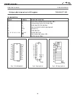
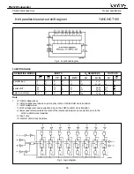
The 74HC/HCT165 are 8-bit parallel-load or serial-in shift
registers with complementary serial outputs (Q
7
and
Q
7
) available from the last stage. When the parallel load
(PL) input is LOW, parallel data from the D
0
to
D
7
inputs are loaded into the register asynchronously.
When PL is HIGH, data enters the register serially at the
D
s
input and shifts one place to the right
(Q
0
→
Q
1
→
Q
2
, etc.) with each positive-going clock
transition. This feature allows parallel-to-serial converter
expansion by tying the Q
7
output to the D
S
input of the
succeeding stage.
The clock input is a gated-OR structure which allows one
input to be used as an active LOW clock enable (CE) input.
The pin assignment for the CP and CE inputs is arbitrary
and can be reversed for layout convenience. The
LOW-to-HIGH transition of input CE should only take
place while CP HIGH for predictable operation. Either the
CP or the CE should be HIGH before the
LOW-to-HIGH transition of PL to prevent shifting the data
when PL is activated.
APPLICATIONS
•
Parallel-to-serial data conversion
QUICK REFERENCE DATA
GND = 0 V; T
amb
= 25
°
C; t
r
= t
f
= 6 ns
Notes
1. C
PD
is used to determine the dynamic power dissipation (P
D
in
µ
W):
P
D
= C
PD
×
V
CC
2
×
f
i
+ ∑
(C
L
×
V
CC
2
×
f
o
) where:
f
i
= input frequency in MHz
f
o
= output frequency in MHz
∑
(C
L
×
V
CC
2
×
f
o
) = sum of outputs
C
L
= output load capacitance in pF
V
CC
= supply voltage in V
2. For HC the condition is V
I
= GND to V
CC
For HCT the condition is V
I
= GND to V
CC
−
1.5 V
ORDERING INFORMATION
See
“74HC/HCT/HCU/HCMOS Logic Package Information”
.
SYMBOL
PARAMETER
CONDITIONS
TYPICAL
UNIT
HC
HCT
t
PHL
/ t
PLH
propagation delay
CP to Q
7,
Q
7
PL to Q
7,
Q
7
D
7
to Q
7,
Q
7
C
L
= 15 pF; V
CC
= 5 V
16
15
11
14
17
11
ns
ns
ns
f
max
maximum clock frequency
56
48
MHz
C
I
input capacitance
3.5
3.5
pF
C
PD
power dissipation capacitance per
package
notes 1 and 2
35
35
pF
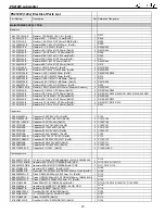
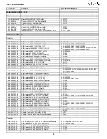
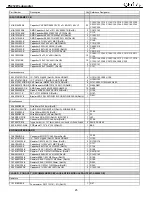
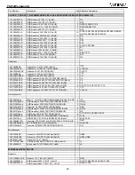
PS212W
subwoofer
31
Summary of Contents for PS212W
Page 5: ...PACKAGING PS212W subwoofer 4...
Page 9: ...PS212W subwoofer 8...
Page 10: ...PS212W subwoofer 9...
Page 17: ...PS212W subwoofer 16...
Page 18: ...PS212W subwoofer 17...
Page 19: ...2 1 3 2 1 3 PS212W subwoofer 18...
Page 20: ...PS212W subwoofer 19...
Page 21: ...PS212W subwoofer 20...
Page 22: ...PS212W subwoofer 21...
Page 23: ...PS212W subwoofer 22...
Page 43: ...PS212W subwoofer 42...
Page 44: ...Green Red D401 LED_5DIA PS212W subwoofer 43...
Page 46: ...VDD U105 C VEE U105 D 6 5 7 U105 B TL072 2 3 1 TL072 U105 A PS212W subwoofer 45...
Page 49: ...L01 56R 2 1 PS212W subwoofer 48...
Page 51: ...PS212W subwoofer 50...
Page 52: ...PS212W subwoofer 51...
Page 53: ...PS212W subwoofer 52...
Page 54: ...PS212W subwoofer 53...
Page 55: ...PS212W subwoofer 54...


