background image

INFLUX BRASIL – Av Paraná, 3059 – Cajuru do Sul — Sorocaba


– São Paulo - CEP:18105-002  Tel.: (15) 3359 9739 (15) 99621


1260 - e-mail: vendas@influxbrasil.com


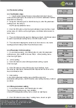
4.4 Parameter setting 
 
4.4.1 Calibration steps 

1

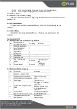
Liquid crystal display the level value after instrument plug in, 

shown as the right figure, the actual level is 3.320m, calibration method 
described as following 
2

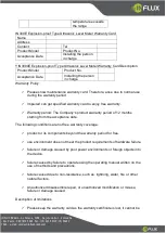
Using the “inductive-pen” to click Mode key to enter the parameter 

setting menu, first entry is 

the P01(level)calibration menu. 


3

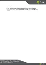
Click the OK button, enter the level calibration input interface, input 

actual value of 3.320m, as the right figure, click Mode button return to 
level menu 


4

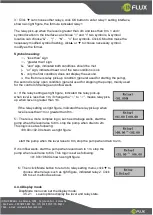
Then click Mode button again to display as shown, click Mode button 

to return to parameter setting menu, click OK button to exit. 


5

The instrument displays the actual level, from then on, the meter 

readings will accurately reflect the actual level value. 


4.4.2 Parameter 4~20mA setting 

1

In a normal operation, click Mode button to enter the parameter 

setting menu, then click▼to choose P02(4

20mA) setting menu, 

shown as right figure. 


2

 20 mA setting 

a

Click OK button to enter 20mA parameter setting, crystal                        

shown as right. 


b

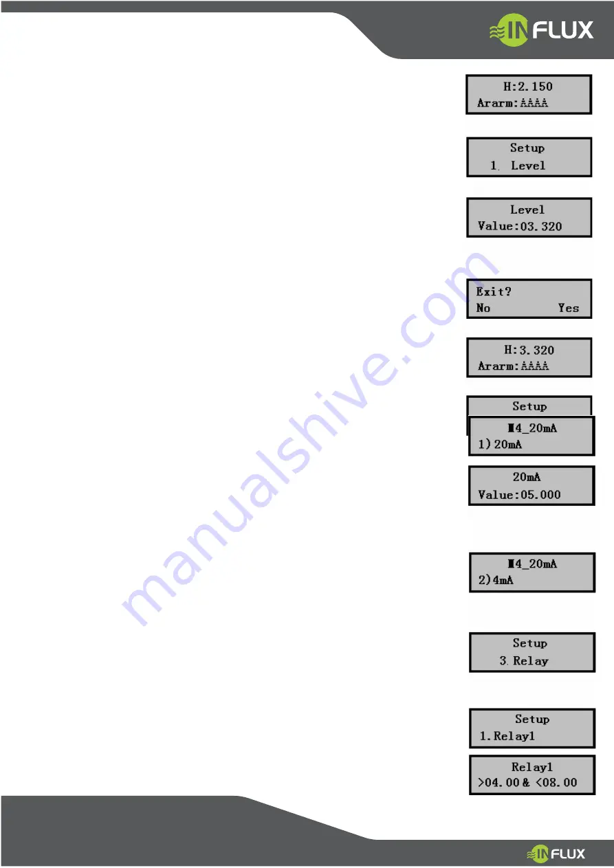
Click OK button to enter 20mA value input interface, input                          

the value as right figure, indicated 20mA output when the level is 5m, 
then click Mode to exit. 


3

4mA setting 

In the 20mA parameter setting menu click▼to enter 4mA                     
parameter setting menu, click OK button enter setting interface, method 
as above. 


4.4.3 Relay parameter setting 

1

In a normal operation, click Mode button to enter 

The parameter setting menu, then click▼to 
choose P03(relay)relay setting menu, shown as right figure. 


2

Click OK button to enter relay 1 setting menu, shown as right 

Summary of Contents for INU300

Page 1: ...RASIL Av Paran 3059 Cajuru do Sul Sorocaba S o Paulo CEP 18105 002 Tel 15 3359 9739 15 99621 1260 e mail vendas influxbrasil com INU300 Touch Screen Ultrasonic Level Meter User Manual www infiuxbrasil...

Page 2: ...ion guide 6 3 3 Principles of installation 6 3 4 Installation notes 6 3 5 Instrument connection 7 4 Instrument debugging 9 4 1 Instrument display 9 4 2 Keyboard 10 4 3 Menu 11 4 4 Parameter setting 12...

Page 3: ...g conditions caused by damage to the product Consumption of items not in the scope of this warranty out Within the scope of this warranty any defects in products will be due to the products not allowe...

Page 4: ...explosion proof and other areas The instrument can be connected to a variety of DCS system through 4 20mA or RS485 Modbus protocol provide real time level data for industrial automation operation INU3...

Page 5: ...on code Type TL300E Measuring range 0 10m Blind spot 0 45m 0 60m Precision 0 3 Resolution 1mm Pressure Under 4 atmospheres Instrument display With LCD display level or space distance Analog output 4 2...

Page 6: ...on the flange 3 3 Principles of installation 3 3 1 Meter mounting height should less than optional instrument range 3 3 1 The distance of transducer emitting surface to the highest level blind spot s...

Page 7: ...hot cold places that ambient temperature may exceed the requirements of the instrument you d better plus anti heat low temperature devices around instrument 3 5 Instrument connection Counterclockwise...

Page 8: ...reverse After plug DC24V power the meter power supply input voltage in not less than 19V The maximum load of 4 20mA output line should be less than 500 4 Instrument debugging The indicators of instru...

Page 9: ...e change data the key as the button to shift 4 2 1 Using the inductive pen notes Use inductive pen to click should close to the glass and hold more than 1 second Click the button when the meter displa...

Page 10: ...INFLUX BRASIL Av Paran 3059 Cajuru do Sul Sorocaba S o Paulo CEP 18105 002 Tel 15 3359 9739 15 99621 1260 e mail vendas influxbrasil com...

Page 11: ...ton to exit 5 The instrument displays the actual level from then on the meter readings will accurately reflect the actual level value 4 4 2 Parameter 4 20mA setting 1 In a normal operation click Mode...

Page 12: ...condition general used for stopping the pump mainly used for the control of drainage and inflow wells 4 If the relay setting as right figure indicated the relay pick up when level is less than 1m if c...

Page 13: ...do not change 5 Equipment list 5 1 Equipment s and accessories provided No Equipment s or accessories name Quantity Remarks 1 GPM B explosion proof ultrasonic level meter 1 2 Operation instruction 1 3...

Page 14: ...d warranty card to enjoy free warranty Warranty period The Company s product warranty period of 12 months starting from the acceptance date The following conditions are not free warranty coverage prod...

Page 15: ...aba S o Paulo CEP 18105 002 Tel 15 3359 9739 15 99621 1260 e mail vendas influxbrasil com reissued This warranty card explains permissions owned by the Company the Company reserves the right to modify...

Reviews: