


INFLUX BRASIL – Av Paraná, 3059 – Cajuru do Sul — Sorocaba
– São Paulo - CEP:18105-002 Tel.: (15) 3359 9739 (15) 99621
1260 - e-mail: vendas@influxbrasil.com
3
)
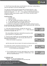
Click ▼ can choose other relays, click OK button to enter relay 1 setting interface,
shown as right figure, the formula indicated relay 1
The relay pick-up when the level is greater than 4m and less than 8m. < and >
symbol location in the interface can choose “<” and “>” two symbols, & symbol
location can choose “&”
、
“|”
、
“N”
、
“
∧
” four symbols. Click OK button make the
necessary modified symbol flashing, click▲ or ▼ to choose necessary symbol,
modify as the former.
Symbol meaning:
<:
“less than” sign
>:
“greater than” sign
&
:
“and” sign, indicated both conditions should be met.
|
:
“or” sign, indicated meet on of the two conditions is ok.
N
:
only the first condition, does not display the second.
∧
:
the first one is relay pick-up condition (general used for starting the pump),
the second is relay open condition (general used for stopping the pump), mainly used
for the control of drainage and inflow wells.
4
)
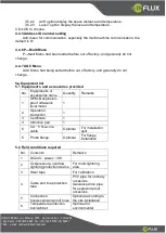
If the relay setting as right figure, indicated the relay pick-up
when level is less than 1m, if change the “
<
” to “
>
”, means relay pick-
up when level is greater than 1m.
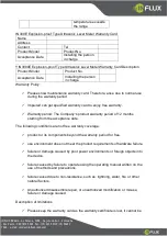
If the relay setting as right figure, indicated the relay pick-up when
level is less than 1m or greater than 9m.
5
)
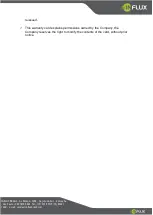
There is a more complex logic, such as drainage wells, start the
pump when the level raise to 8m, stop the pump when drain to 2m.
This logic is set as following:
>08.00
∧
<02.00 shown as right figure.
start the pump when the level raise to 8m, stop the pump when drain to 2m.
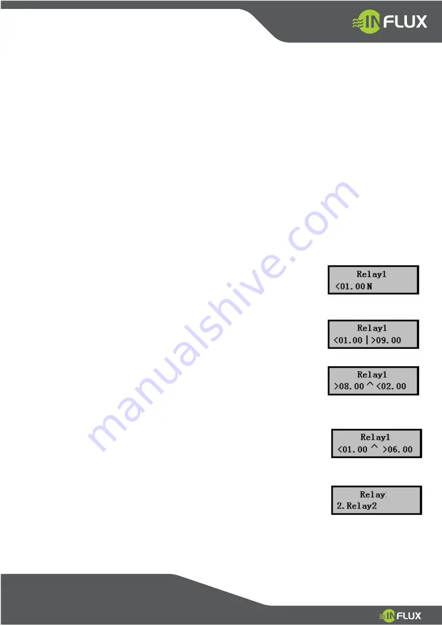
If it is inflow wells, start the pump when level down to 1m, stop the
pump when level raise to 6m. This logic is set as following:
<01.00
∧
>06.00 shown as right figure.
6
)
Then click Mode button to return to relay setting menu, click ▼ to
choose other relays: such as right figure, indicated relay 2. Click
OK to set, method as above.
4.4.4 Display mode
DispMode menu can set the display mode:
3.5.2.1
Level options display the level and relay state.


