background image


InfluxGreen Energy Pte Ltd


Model:


IGSI-3 Phase  Output Ser ies


        Rev. 0 


8

Opening the package 


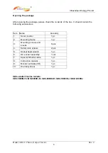
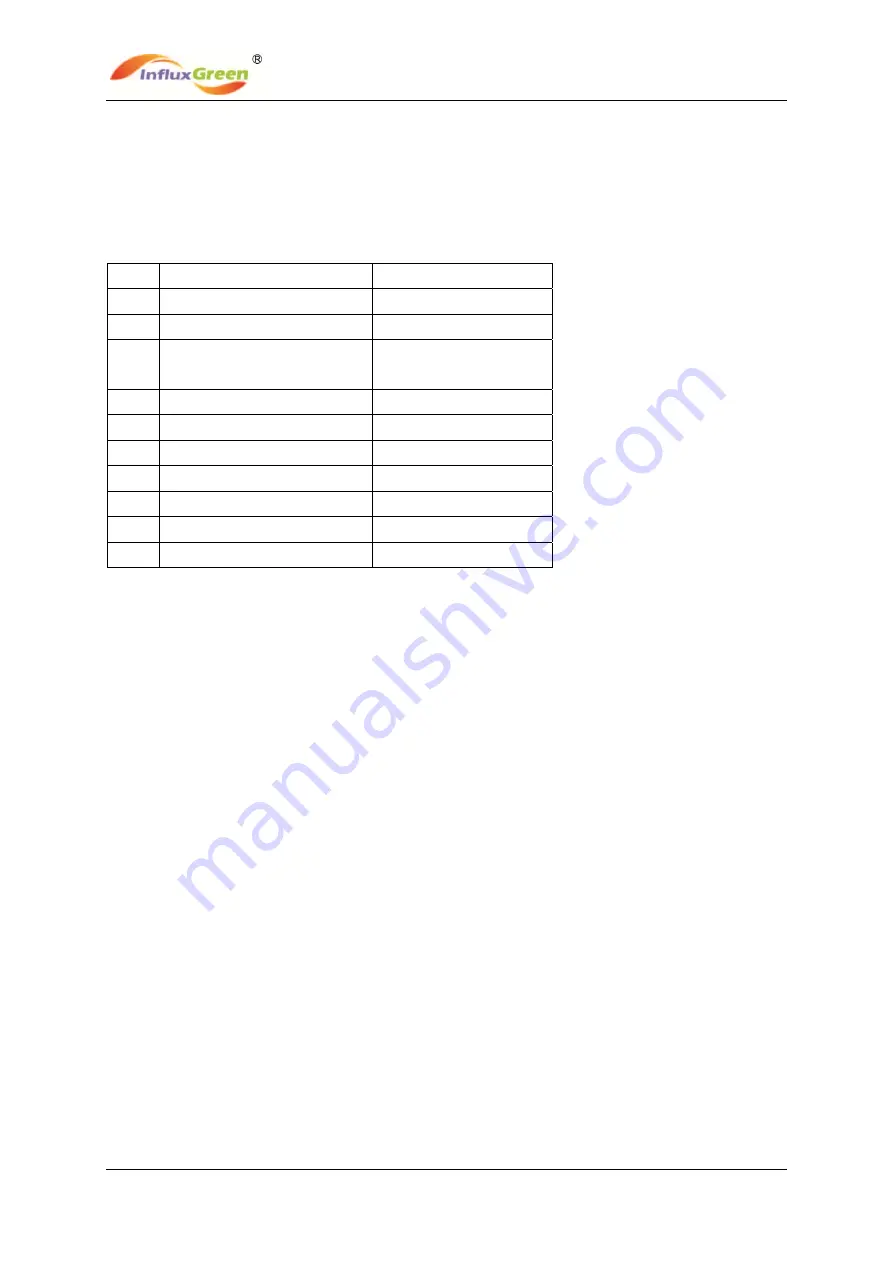
After opening the package, please check the contents of the box. It should contain the 
following accessories: 


Item Name 

Quantity 

1. Solar 

inverter 

pc 

2. Mounting 

frame 

pc 

3. 

Mounting screws and 
blocks 

6 pcs 

4. Safety-lock 

screws 

pcs 

5. 

Socket head wrench 

1 pc 

6. DC 

socket 

assembly 

set 

7. Special 

RS-232 

cable 

pc 

8. Instruction 

manual 

pc 

9. 

Monitor software(CD) 

1 pc 

10. Warranty 

sheet 

pc 


IGSI-xxxxDJ/3 series include:   
IGSI-5000DJ/3, IGSI-6000DJ/3, IGSI-8000DJ/3, IGSI-10000DJ, IGSI-12000DJ


Summary of Contents for IGSI - 3 Series

Page 1: ...Green Energy Pte Ltd Model IGSI 3 Phase Output Series Rev 0 1 INSTALLATION AND OPERATIONS MANUAL IGSI 3 Phase Output Series IGSI 5000DJ 3 IGSI 6000DJ 3 IGSI 8000DJ 3 IGSI 10000DJ IGSI 12000DJ IGSI xxx...

Page 2: ...TABLE Document Revision Author Date Change Description 0 KL Tan 01 06 2012 First release SAVE THESE INSTRUCTIONS IMPORTANT SAFETY INSTRUCTIONS NOTE Reproduction and disclosure of the contents of this...

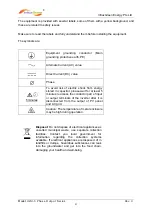
Page 3: ...fied service personnel As a qualified service personnel you should know both ac and dc voltage sources are terminated inside this units Each circuit must be individually disconnected before servicing...

Page 4: ...from energy stored in capacitor please wait for at least 5 minutes to access the conductor part of input or output terminals of the inverter after it is disconnected from the output of PV panel and A...

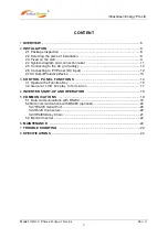
Page 5: ...2 2 6 Connecting to PV Panel DC input 12 2 7 AC Output Protective Device 13 3 CONTROL PANEL FUNCTIONS 14 3 1 Operate the Function Key 15 3 2 General LCD Display Information 17 4 INVERTER START UP AND...

Page 6: ...d DSP control technology Utilize the latest high efficiency power component Optimal MPPT technology 2 independent MPP trackers Advanced anti islanding solutions Maximum efficiency up to 98 EU efficien...

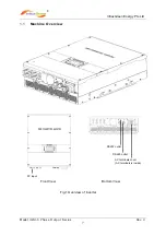
Page 7: ...een Energy Pte Ltd Model IGSI 3 Phase Output Series Rev 0 7 1 1 Machine Overview Front View Bottom View Fig 1 Overview of inverter RS232 outlet AC terminals cover AC terminals is inside RS 485 outlet...

Page 8: ...ssories Item Name Quantity 1 Solar inverter 1 pc 2 Mounting frame 1 pc 3 Mounting screws and blocks 6 pcs 4 Safety lock screws 2 pcs 5 Socket head wrench 1 pc 6 DC socket assembly 1 set 7 Special RS 2...

Page 9: ...all shipping material for the event the carrier sends an inspector to verify damage If the inspection reveals damage to the inverter please call your local supplier or the authorized distributor They...

Page 10: ...installed position of the inverter 2 3 Fixed on the wall Step1 Drill 6 or 9 holes as illustrated in the Fig 4 Step2 Fix the mounting frame as illustrated in the Fig 5 by the screws and then hang the...

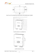
Page 11: ...Green Energy Pte Ltd Model IGSI 3 Phase Output Series Rev 0 11 Fig 4 The size of mounting frame for IGSI xxxxDJ 3 IGSI 10000DJ IGSI 12000DJ Fig 5 Hang inverter to mounting frame Fig 6 Fix safety lock...

Page 12: ...and Connection Label The IGSI DJ 3 series are three phase solar inverters with two independent channels of MPPT input They are designed to convert the direct current generated by PV panels into three...

Page 13: ...y they may consist of electrical breaker fuse and or connecting terminals To comply with local safety standards and codes the connection system should be designed and implemented by a qualified techni...

Page 14: ...RNING Use suitable low impedance cables to connect the inverter to AC disconnect WARNING IGSI DJ 3 phase series inverter shall be connected to AC disconnect by means of a five wire cable three phase c...

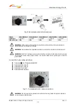
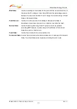
Page 15: ...nd the DC Switch to the terminals of the inverter please ensure that the polarity is correct Incorrect polarity connection could permanently damage the unit Please confirm the short circuit current of...

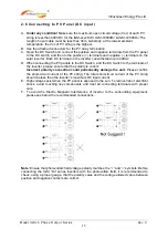
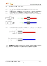
Page 16: ...esponding crimping notch and crimp the contact 2 6 1 3 Insert the core tube into the slot of the connection until you hear the locking sound indicating in connection is in place 2 6 1 4 Insert contact...

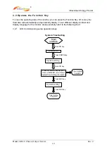
Page 17: ...he inverter D POWER LED Indicates the inverter is running normally E Fault LED Indicates the fault of the inverter F Function Key Shall be used to set different parameters and display language for the...

Page 18: ...ault Recover Inverter is on the process of circulating in take place mistake or breakdown break down Inverter to re combine a net after the relief Normal State Inverter feeds to grid energy from PV pa...

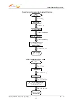
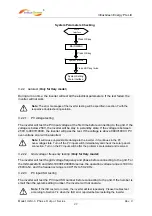
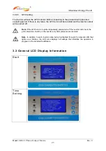
Page 19: ...lay To set different display contrast and display language for the inverter please carefully refert to the following chart 3 2 1 LCD Commissioning setup operation steps System Time Setting Main Interf...

Page 20: ...ess OK key Select your language Language Setting Complete System Setting Main Interface Press UP DOWN key Press OK key Press ESC key twice System setting Main Interface Press OK key Press UP DOWN key...

Page 21: ...nergy Interface Press OK key System Setting Main Interface Press UP DOWN key MAIN MENU Press OK key Press UP DOWN key Press ESC key twice System setting Energer Diagram Main Interface Press OK key Pre...

Page 22: ...I 10000 120000DJ series the operating voltage range is 190V to 260V L N and the frequency range is 49 71Hz to 50 29 Hz 3 2 2 3 PV input ISO testing The inverter will test the PV input ISO number befor...

Page 23: ...verter output will be turned off Note In addition to each inverter state being highlighted through the relevant LED that lights up or flashes the LCD also displays a message that identifies the operat...

Page 24: ...InfluxGreen Energy Pte Ltd Model IGSI 3 Phase Output Series Rev 0 24 System Setting System Status Main Menu...

Page 25: ...InfluxGreen Energy Pte Ltd Model IGSI 3 Phase Output Series Rev 0 25 Auto Test Menu for Italy Auto Test Submenu for Italy Default Display...

Page 26: ...InfluxGreen Energy Pte Ltd Model IGSI 3 Phase Output Series Rev 0 26 History Record Power Data Reset Energy Diagram Menu...

Page 27: ...Rev 0 27 Energy Diagram 3 4 State Message In LCD State Message In LCD STATE DISPLAY CONTENT COMMENTS Wait State While PV Voltage 250V Inverter Checking Relay Off PreChecking State While checking to 0...

Page 28: ...nd display error message Auto Test State only for Italy Protection auto test Main Operating Messages In LCD STATE DISPLAY CONTENT COMMENTS Normal display Display power Etoday Etotal System Status Disp...

Page 29: ...is sufficient Once the solar inverter starts it enters one of the following 3 states in turn Standby The PV string can only provide just enough voltage to minimum requirements of the internal controll...

Page 30: ...blem of PV panel 5 GFCI Fault leakage current is too high 6 Grid Freq Fault Grid frequency is out of range 7 Grid Volt Fault Grid voltage is out of range Inverter fault 1 Consistent Fault Consistent f...

Page 31: ...le from the local market 5 2 Data communication with RS485 optional 5 2 1 RS485 Serial Port The RS485 is used for the purpose of communicaiton between several inverters Ethernet cable is connetced to...

Page 32: ...cable with RJ45 connector The output ethernet cable will be connected to the next unit The RS485 pin definition is as follows RJ45 connectors Pin Signal Name Description 1 Not Used 2 Not Used 3 RTN S...

Page 33: ...r and a vacant RJ45 socket are provided in the attached accessories If the inverter is not the last one in the chain please remove the terminal resistor and use it as a vacant RJ45 socket In order to...

Page 34: ...ts Disconnection is provided in case of any hardware malfunctioning The solar inverter will cease to energize the AC grid in response to an interface protection and it is achieved by the simple isolat...

Page 35: ...Inverter is earthed The impedance must be greater than 2M 5 GFCI Fault The leakage current is too high Unplug the inputs from the PV string and check the peripheral AC system 6 Grid Volt Fault Make su...

Page 36: ...Frequency Range Hz 50 5 Power Factor 0 9 leading to 0 9 lagging Current Harmonic Distortion THDi 3 Max Efficiency 97 6 97 8 98 1 European Efficiency 96 7 96 9 97 3 MPPT Efficiency 99 6 Environment Par...

Page 37: ...0 5 Power Factor 0 9 leading to 0 9 lagging Current Harmonic Distortion THDi 3 Max Efficiency 98 2 98 3 European Efficiency 97 6 97 6 MPPT Efficiency 99 6 Environment Parameters Protective Level IP65...

Reviews: