

I n t r o d u c t i o n
The Vega patio heater produces radiant heat like the sun, warming people and objects and not the air in between, providing
the only form of heat that will not blow away. The Vega is primarily designed for outdoor use within domestic applications and
is therefore weatherproof.
Please read the following instructions carefully before use. The safety of this heater is guaranteed only by its correct
usage in accordance with these instructions, therefore it is recommended that they are retained for future reference.
C a u t i o n
Before using this appliance:
Check that the voltage indicated on the type plate corresponds to the mains supply voltage.
Ensure that the heater has been securely fastened in its final mounting position.
Disconnect the power during installation, cleaning and/or filament replacement and ensure
that the filament is cool.
Do not handle the filament with bare hands. If it is inadvertently touched, remove finger marks
with a soft cloth and methylated spirit or alcohol, otherwise the marks will burn into the quartz,
causing premature heater failure.
Touch the front glass as little as possible in order to avoid unsightly grease residue.
Do not use an extension cable with this product.
Keep the mains cable away from the body of the heater which will get hot during use.
Do not cover or obstruct the heater when in use.
Ensure that children do not tamper with the heater.
Do not insert any object through a slot or opening in the heater.
Do not use if glass is broken.
For the US/Canada - Use only on 15 ampere branch circuit.
Do not install less than 2.3m (7’7”) from the floor.
R i s k o f f i r e
Keep combustible materials such as furniture, papers, clothes and
curtains at least 3 feet (0.9m) from the front of the heater and
away from the sides and rear. If the heater is to be used outside,
we recommend that a waterproof or indoor socket is used.
Specification
VEGA
VEGA USA
Voltage (V)
230
120
Total power (kW)
1.3
1.2
Phase supply
1(230V)
1(120V)
Amps per phase (A)
5.7
10
Minimum mounting height from floor
2.3m
7’ 7’’
Minimum distance from ceiling
0.5m
1’ 7’’
Minimum distance from side wall
1.5m
4’ 11’’
Dimensions W x H x D
410mm x 210mm x 130mm
16 ’’ x 8¼’’ x 5”
Weight
2.85kg
6
1/4
lb
Insulation class
1
1
Ingress protection
IP54
IP54
* All measurements are nominal and subject to change without prior notification
0.9m
2.8m (9’ 2’’)
2.8m (9’ 2’’)
2.
8m
(
9’
2
’’)
8m
2
2.
3m
(
7’
7
’’)
M
in
im
um
m
ou
nt
in
g
he
ig
ht
I n s t a l l a t i o n
W i r i n g
Warning - this appliance must be earthed or grounded.
The wired versions (VEGA and VEGA USA) are fitted with 5 metres (16’5”) of supply cable and a moulded plug,
therefore it is unnecessary to remove the terminal box in order to carry out normal installation of these models.
All installations (wired and unwired) must be carried out by a suitably qualified electrician, following the instruction
below, in accordance with relevant local safety regulations.
We recommend using a RCD or GRD where applicable.
If the supply cord becomes damaged, it must be replaced by the manufacturer, its service agent or a similar
qualified person in order to avoid a hazard.
When the electrical connection is outside, it is recommended that a waterproof socket is used for the connection/
terminal. Otherwise, the plug should be connected to a socket indoors.
If in any doubt, please contact a suitably qualified electrician.
1.
Disconnect power. Unscrew the terminal box cover at the back of the
heater and feed the supply cable through the compression gland.
2.
Use a heat resistant supply cable with 2 poles and earth. The live and
neutral wires must be covered with the protective silicon casing provided
before connection to the terminal block. See Fig 1.
3.
The green/yellow wire should be connected to the clamp marked with
the earth or ground symbol.
4.
Tighten the barrel nut of the compression gland so that the rubber seal
grips the cable. The seal can be adjusted to accommodate cables of
diameter between 8mm and 11mm (approx ’’). See Fig 2.
5.
Ensure that the cover is secured well in order to prevent water ingress.
M o u n t i n g
1.
Separate the heater from the mounting bracket by loosening the 2 nuts
on the back of the heater.
2.
Securely fasten the bracket to the mounting surface using the fixing
holes in the mounting bracket. The torque of the bracket fastening
screws must be at least 8 Nm.
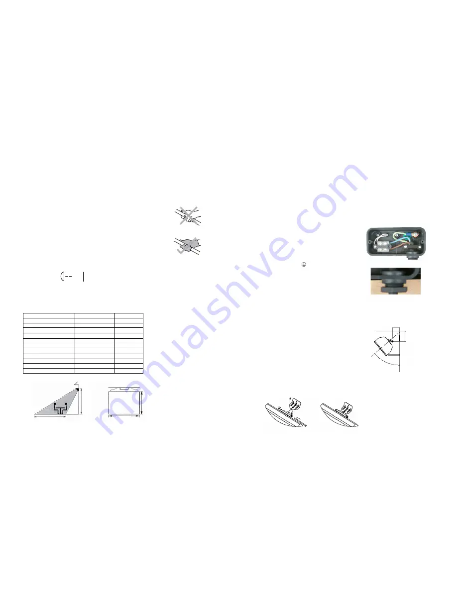
3.
Replace the heater on the bracket using the nut and bolt supplied (Fig 4
and 5) and fix at the required angular position by tightening the fixing
bolt (Fig 3).
The heater must be mounted in such a way that the halogen emitter
does not slant more than 4° from the horizontal (when viewed from the
front of the heater).
Allow the heater to cool before attempting to reposition/move. Never
attempt to move the heater while it is switched on.
The heater is suitable for installation on a normally non-flammable
surface. Observe the minimum safe distance between the heater body
and inflammable surfaces when mounting.
Please refer to Table 1 for the recommended positioning of the heater.
Keep out of the reach of children.
Fig 1
Fig 2
Fig 3
0.5m (1’7 ”)
50mm (2”)
50°
Fig 4
Fig 5


