-
11
-
ELECTRICAL CONNECTIONS
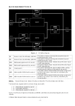
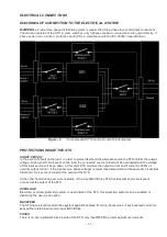
DIAGRAMS OF CONNECTION TO THE ELECTRICAL SYSTEM
WARNING:
a 4-wire three-phase distribution system is required for three-phase input and output connections.
The standard version of the STS (3 pole) switches only 3 phases neutral is connected to the output directly. 3-
phase power line + n protective earth (PE), in compliance with the IEC 60364-3 specifications.
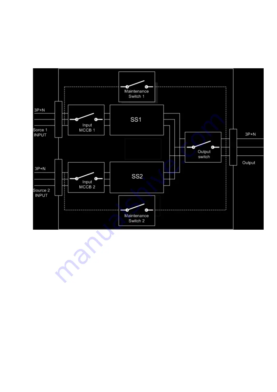
Figure – 6
3 pole standard STS input and output block diagram
PROTECTIONS INSIDE THE STS
SHORT CIRCUIT
In the event of a fault on the load , in order to protect itself and the alternate source the STS inhibits the output
voltage. During short circuit event on the load, the connected source to load will be overloaded and the voltage
of this input source will be go down, at this point STS monitors the output current and if current is 200% of
nominal output current , if the input source phase voltages is lower than allowed limit at the same time it decides
that short circuit event occurred at the output of the STS.
At the other hand during over current status , if the input MCCB trips STS decides that short circuit event
occurred at the output of the STS.
OVERLOAD
Electronic overload protection system is used inside of the STS ,this protection system can be enabled or
disable by the user as an option.
BACKFEED
The STS have electronic protection system against backfeed from any input source ,if any backfeed current is
sensed the related input source input MCCB trips.
FUSES
There is no any replacable fuses inside of the STS ,only input MCCB’s protect against overcurrents.
Summary of Contents for InfoSTS
Page 45: ...44 Figure 28...
Page 47: ...NOTES...


