16
4.2.1.3. Bypass Input Connection
Please add four-pole (4-pole) circuit breaker (equivalent UPS Bypass breaker) to distribution panel
where
UPS is to be connected.
Connect the phase cables to
Bypass
L1-L2-L3
terminals, the neutral to
Bypass
N
terminal. Neutral connection
should be done directly from distributon neutral bus to UPS neutral.
4.2.1.4. Battery Connection
If the batteries are already built-in inside the UPS cabinet; remove the cover of UPS and connect the
Positive
(red), Negative (black) and Neutral (blue
) cables of the batteries. There is no need any further connection so
replace the cover.
If the batteries shall be put in a separate additional battery cabinet, please follow up the instructions below;
•
Connect between battery circuit breaker and battery terminals with using proper cross-section
Positive
(red), Negative (black) and Neutral (blue)
cables.
•
Switch on to
“
0
”
position the battery cabinet circuit breaker.
•
Connect the
“
-
“
on the battery cabinet to
“
-
“
on the UPS.
•
Connect the
“+“
on the battery cabinet to
“+“
on the UPS.
•
Connect the
“N“
on the battery cabinet to
“N“
on the UPS.
Bring the circuit breaker on the
distribution panel to “OFF”
position before making the
connections
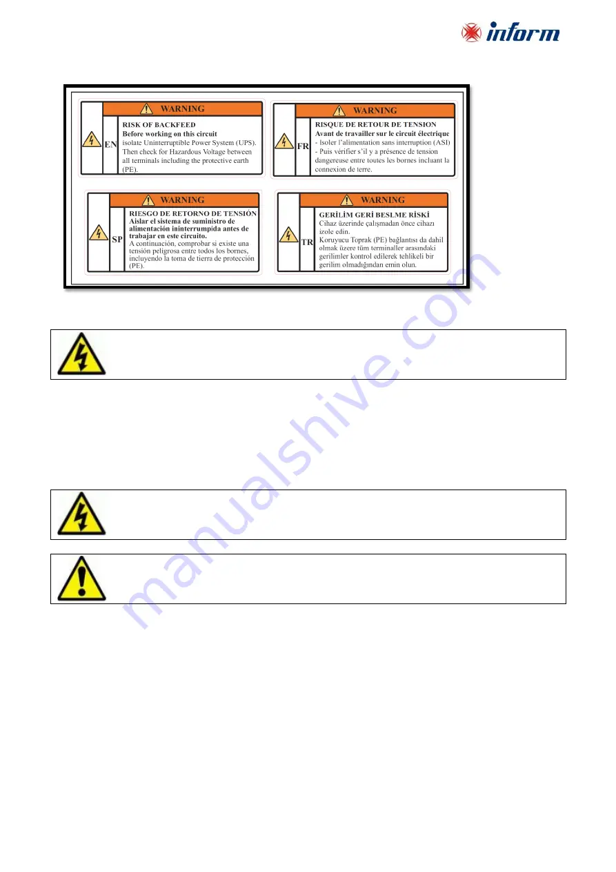
Devices with internal batteries may have dangerous voltages on the battery terminals.
Do not switch the battery circuit breaker (F5) to
ON
position before operating the equipment
and seeing “
Online Operation
” message on the LCD.


