30
6.1. Front Panel Segments
Front panel consists of two segments:
Colour Touchscreen Graphical Control Panel
and
UPS Status LED Bar
offers detailed information about UPS.
6.1.1. Colour Graphical Touchscreen
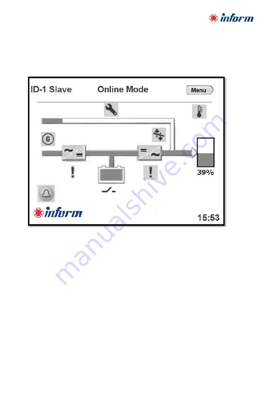
ENERGY FLOW DIAGRAM/MODES OF OPERATION
and
MENUs
are displayed on LCD.
The description of the symbols in the energy flow diagram:
1.
Bypass Input:
If Bypass voltage is OK and synchronizes with inverter; it lits Green, If Bypass voltage is OK
and not synchronizes with inverter; it lits Orange.
2.
Rectifier Input:
If Input voltage is OK, it lits Green.
3.
Rectifier:
Converts AC voltage at the input into DC voltage. You may reach the rectifier measurements by
touching it.
4.
Bypass Line:
Shows that the loads are supplied via Bypass and line colour is Orange. If UPS is on Eco
Mode it is Green.
5.
Battery:
Shows battery conditions. If it is discharging the indicator goes down, if it is charging the
indicator goes up. You may reach the battery/DC measurements by touching it.
6.
Inverter:
Converts DC voltage into AC voltage. You may reach the output measurements by touching it.
7.
Operation Mode Information:
Shows UP
S’s current operation mode.
8.
Load:
Shows the percentage of the load as numerical and graphical information. If there is overload at
the output the load graphic lits Red. You may reach the output power measurements by touching it.
9.
Menu:
You may reach the menus by touching it.
10.
Configuration:
It indicates if UPS is in parallel or single operation configuration. At Single Mode; there is
no symbol.
11.
Time:
It indicates the time.
10
7
0
2
3
6
6
0
1
0
8
5
4
9
12
11
13
14
15
17
16
18


