background image

INFOSEC UPS SYSTEM - 15, rue du Moulin - 44880 Sautron - FRANCE - www.infosec-ups.com 

Hot Line – Tel + 33 (0)2 40 76 15 82 - Fax + 33 (0)240 94 29 51 - hotline@infosec.fr – 07 19 AA 36 205 10 

17 


User guide 


1 .   S A F E T Y   I N S T R U C T I O N S   –   S e c u r i t y  


IMPORTANT! 

Save this manual properly and read carefully the following instructions before installing the unit. 

Do not operate this unit before reading through all safety information and operating instructions 

carefully. Installation and Wiring must be performed in accordance with the local electrical laws 

and  regulations.  Installing  and  connecting  UPS  system  in  a  way  that  does  not  comply  with 

accepted practices releases Infosec Communication from any liability.  


Transportation  

1.  Please transport the UPS system only in the original package to protect against shock and 

impact. 


Preparation and good disposals of the device: 

1.  Condensation  may  occur  if  the  UPS  system  is  moved  directly  from  cold  to  warm 

environment. The UPS system must be absolutely dry before being installed. Please allow 

at least two hours for the UPS system to acclimate the environment.  

2.  Do not install the UPS system near water or in moist environments.  

3.  Do not install the UPS system where it would be exposed to direct sunlight or near heater.  

4.  Do not block air vents in the housing of UPS. The UPS must be installed in a location with 

good ventilation. Ensure enough space on each side for ventilation. 

5.  Do not block the air vents of the UPS. In order for the UPS to function safely, it should be 

installed in a well ventilated, non confined area for the optimal room air circulation. Leave 

enough space around it on each side for ventilation. 

6.  Do not place anything on top of the UPS and leave a space of about 20cm around it on all 

sides, otherwise there is a risk that it may overheat or even cause a fire. 

7.  The  mains  outlet  that  supplies  the  UPS  must  be  located  near  the  UPS  and  be  easily 

accessible. 

8.  Install the UPS in a temperature and humidity-controlled room free of conductive interference. 

9.  Disconnect the UPS from AC power and switch it off before cleaning with a damp cloth (no 

cleaning products). 

10.  Do not leave any recipients containing liquid on or near the UPS. 

11.  Place cables in such a way that no one can step on or trip over them.  

12.  Prevent no fluids or other foreign objects from inside of the UPS system 


Risk of electric shock:


1.  The  UPS  unit  uses  potentially  hazardous  voltages.  Do  not  attempt  to  disassemble  this 

equipment as it does not contain accessible components that can be repaired by users, fuse 

change excepted.  

2.  Caution  -risk  of  electric  shock.  The  battery  circuit  is  not  isolated  from  the  input  voltage. 

Hazardous  voltages  may  occur  between  the  battery  terminals  and  the  ground.  Before 

touching, please verify that no voltage is present! 

3.  The  UPS  system  operates  with  hazardous  voltages.  Repairs  may  be  carried  out  only  by 

qualified maintenance personnel.  

4.  The utility power outlet must be near the equipment and be easily accessible. To isolate the 

UPS from AC input and swith it off, remove the plug from the utility power outlet.  

Summary of Contents for 66092N1

Page 1: ...2200 3000 VA Notice d utilisation________________________ 2 User guide _____________________________ 17 Gu a de usuario _________________________ 32 Bedienungsanleitung_____________________ 47...

Page 2: ...oit tre install dans un local bien ventil et non confin pour une circulation optimale de l air ambiant Laisser suffisamment d espace de chaque c t pour l a ration 5 Ne rien poser sur l onduleur et lai...

Page 3: ...on u pour des ordinateurs personnels Il ne doit pas tre utilis avec des appareils lectriques ou lectroniques comportant des charges inductives telles que moteurs ou lampes fluorescentes 7 Ne pas conne...

Page 4: ...ions d installations et d environnement Ces renseignements sont not s sur le bon de garantie ou inscrits sur la plaque signal tique l arri re de l appareil Vous pouvez galement les reporter dans le ca...

Page 5: ...s batteries usag es 2 INSTALLATION ET CONFIGURATION REMARQUE Il est recommand que l installation soit effectu e par un technicien qualifi Inspecter l unit avant de l installer S assurer que rien n est...

Page 6: ...00 VA face arri re Sch ma 3 E3 Live 2200 3000 VA face avant 1 Disjoncteur d entr e 2 Prise d alimentation 3 Prises de sortie IEC 4 Slot intellignent SNMP 5 Connecteurs RJ45 11 6 Connecteur de fonction...

Page 7: ...version rack tape 1 Installation des oreilles de montage en rack Fixez les deux oreilles de montage en rack l onduleur l aide des 8 vis M4 X 8 L fournies tape 2 Installation de l onduleur sur le rack...

Page 8: ...07 19 AA 36 205 10 8 Montage en version tour tape 1 Fixation des plaques de support Serrez les vis 4 vis M5 X 12 des plaques de support oreilles de montage en rack en bas de l onduleur tape 2 Fixatio...

Page 9: ...la capacit totale de l onduleur sur une seule prise de sortie charge sup rieure 10A tape 3 Connexion de communication Ports de communication Port USB Port RS232 Slot intelligent Dans le but de contr l...

Page 10: ...ur jusqu entendre un bip sonore Le voyant bleu interne au bouton poussoir va s allumer en bleu tape 7 Interface USB 1 Logiciel de surveillance Power Master Pour viter l extinction brutale de votre ord...

Page 11: ...ion Microsoft Mac Linux Pour t l charger plus d informations rendez vous sur notre site web www infosec ups com 3 U T I L I S AT I O N 3 1 Fonctions de boutons Boutons Boutons Fonctions Bouton POWER M...

Page 12: ...au LCD Mode batterie Mode secteur Erreur Son d sactiv Appuyez sur le bouton mute pendant 3 sec pour d sactiver et activer l alarme sonore Mode batterie Capacit de la batterie Mode secteur 1 Batterie e...

Page 13: ...EPO activ Code d alarme A18 Temp rature excessive 4 D P AN N AG E Utiliser le tableau ci dessous lorsque l onduleur ne fonctionne pas correctement Probl me Causes possibles Solution Anomalie Secteur...

Page 14: ...duleur Si le probl me persiste contactez l assistance technique Code d erreur F07 Tension INV lev e Code d erreur F08 Tension INV faible Code d erreur F09 Court circuit en sortie L quipement que vous...

Page 15: ...pi ce qui n cessite une intervention de la part de l utilisateur Les batteries doivent tre remplac es lorsque leur dur e de vie de 3 5 ans dans une temp rature ambiante de 25 C a t d pass e G n ralem...

Page 16: ...sions maximales P x L x H mm 430 x 438 x 88 Poids kg 16 7 21 8 Batterie Batterie au plomb tanche 24 Vdc Batterie plomb tanche 12V 9Ah x2 24V 12V 7Ah x4 24V Temps de recharge typique 8 heures Alarmes e...

Page 17: ...ir vents of the UPS In order for the UPS to function safely it should be installed in a well ventilated non confined area for the optimal room air circulation Leave enough space around it on each side...

Page 18: ...ousehold appliances such as microwaves vacuum cleaners hair dryers or life support systems to the UPS 8 Due to excessive consumption laser printers should not be connected to the UPS 9 Please replace...

Page 19: ...rchase E3 Live RT Please keep the original packaging It will be required in the event the USP is returned to the After Sales Department CE conformity This logo means that this product answers to the E...

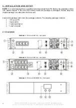
Page 20: ...n install the UPS Before the installation of the unit please inspect it Be sure that nothing inside the package is damaged Please keep the original package in a safe place for future use Unpack the pa...

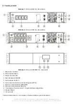
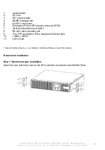
Page 21: ...lligent slot 5 RJ45 11 connectors 6 Emergency Power Off function connector EPO 7 USB communication port HID 8 RS 232 communication port 9 On Off pushbutton Blue integrated indicator light 10 Mute butt...

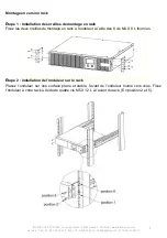
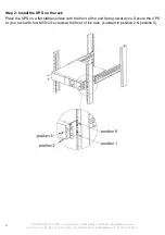
Page 22: ...76 15 82 Fax 33 0 240 94 29 51 hotline infosec fr 07 19 AA 36 205 10 22 Step 2 Install the UPS on the rack Place the UPS on a flat stable surface with the front of the unit facing toward you Secure th...

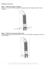
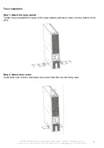
Page 23: ...2 Fax 33 0 240 94 29 51 hotline infosec fr 07 19 AA 36 205 10 23 Tower installation Step 1 Attach the base stands Tighten the screws M5X12 4pcs of the base stands rackmount ears onto the bottom of the...

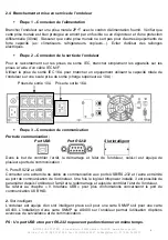
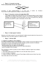
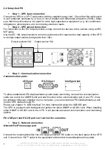
Page 24: ...load greater than 10A Step 3 Communication connection Communication ports USB port RS 232 port Intelligent slot To allow unattended UPS shutdown start up and status monitoring connect the communicati...

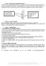
Page 25: ...n battery mode and at the end of its operating time the UPS s USB port can be connected to the computer allowing it to control the status of the UPS Visual alarm in the event of a power failure Automa...

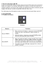
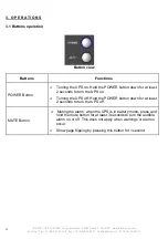
Page 26: ...OWER Button Turning the UPS on Hold the POWER button down for at least 2 seconds to turn the UPS on Turning the UPS off Hold the POWER button down for at least 2 seconds to turn the UPS off MUTE Butto...

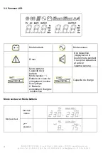
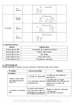
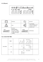
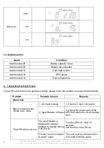
Page 27: ...29 51 hotline infosec fr 07 19 AA 36 205 10 27 3 2 LCD panel Bat mode Line mode Fault Sound disable Press the mute key 3s to disable and enable the Buzzer sound Bat mode Battery Capacity Line mode 1...

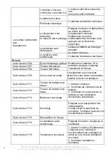
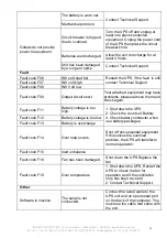
Page 28: ...U B L E S H O O T I N G If the UPS system does not operate correctly please solve the problem by using the table below Problem Possible Causes Remedy Abnormal Mains normal but not Works in AC mode 1...

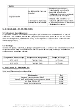
Page 29: ...Volt low Fault code F09 Output circuit short Your attached equipment may have problems please remove them and check again Fault code F11 Battery voltage is too high 1 Shut down the UPS 2 Check the cou...

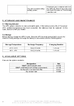
Page 30: ...e life 3 5 years at 25 C ambient temperature has been exceeded the batteries must be replaced In this case please contact your dealer 5 2 Storage Before storing charge the UPS 5 hours Store the UPS co...

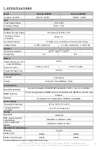
Page 31: ...sical Dimensions HxDxW 88mm x 430mm x 438mm Weight Kg 16 7 21 8 Battery Sealed Maintenance Free Lead Acid Battery 24Vdc Type and number 12V9Ah x 2 24V 12V7Ah x 4 24V Typical Recharge Time 8 Hours Warn...

Page 32: ...uesto a la luz solar directa o cerca de fuentes de calor 4 No bloquee las rejillas de aire en la carcasa del UPS El UPS debe instalarse en una ubicaci n con ventilaci n adecuada Aseg rese de que exist...

Page 33: ...Aseg rese de que la carga conectada no supere las posibilidades del UPS Para asegurar la mejora del tiempo de autonom a y una mayor vida til de la bater a recomendamos una carga equivalente de 1 3 de...

Page 34: ...al Departamento Post Venta tenga preparada la siguiente informaci n ya que se le requerir independientemente del problema Modelo del sistema ininterrumpido de potencia UPS n mero de serie y fecha de c...

Page 35: ...e significa que tambi n deben ser desechadas en un lugar adecuado al final de su vida til P ngase en contacto con el centro de residuos peligrosos y reciclaje local para obtener m s informaci n acerca...

Page 36: ...VA front panel 1 Disyuntor de entrada 2 Entrada de CA 3 Enchufes de salida IEC 4 Ranura inteligente SNMP 5 Conectores RJ45 11 6 Conector de funci n de apagado de emergencia EPO 7 Puerto de comunicaci...

Page 37: ...so 1 Instale las orejas en rack Las orejas de montaje en rack est n adjuntas en el UPS usando las 8 piezas de tornillos proporcionados M4X8L Paso 2 Instale el UPS en el rack Coloque el UPS en una supe...

Page 38: ...07 19 AA 36 205 10 38 Instalaci n de torre Paso 1 Sujete los soportes de la base Apriete los tornillos 4 piezas M5X12 de los soportes de la base orejas de montaje en en el rack a la parte inferior de...

Page 39: ...Utilice el tomacorriente de salida IEC 16 A para conectar un equipo que utiliza la capacidad total del sistema de alimentaci n en un solo tomacorriente de salida carga superior a 10 A Paso 3 Conexi n...

Page 40: ...s para encender el sistema ininterrumpido de potencia UPS Nota La bater a se carga totalmente durante las primeras cinco horas de operaci n normal No espere que la bater a funcione a toda su capacidad...

Page 41: ...perativo Microsoft Mac Linux Para descargar m s informaci n consulte el sitio web www infosec ups com 3 1 Operaci n de los botones Bot n Botones Funciones Bot n POWER Puesta en marcha del sistema de a...

Page 42: ...42 3 2 Panel de LCD Modo de bater a Modo de l nea Falla Desactivar sonido Presione la tecla de silencio 3 segundo para desactivar y activar el sonido de timbre Modo de bater a Capacidad de bater a Mo...

Page 43: ...Si el sistema sistema ininterrumpido de potencia UPS no funciona correctamente resuelva el problema usando la tabla deabajo Problema Causas posibles Soluci n Anormal Red normal pero no funciona en mod...

Page 44: ...jo de INV C digo de falla F09 Cortocircuito de salida El equipo adjunto podr a tener problemas elim nelos y compruebe otra vez C digo de falla F11 El voltaje de bater a es muy alto 1 Apague el UPS 2 C...

Page 45: ...ter a 3 5 a os a una temperatura ambiente de 25 C se debe reemplazar En este caso p ngase en contacto con su distribuidor 5 2 Almacenamiento Antes de almacenar cargue el sistema ininterrumpido de pote...

Page 46: ...IEC enchufes 10 A 1 x IEC 16A F sico Dimensiones DxWxH mm 430 x 438 x 88 Peso kg 16 7 21 8 Bater a Bater a 24 V CC cido de plomo gratuita de mantenimiento herm tico Tipo y n mero 12 V 9 Ah x 2 24 V 12...

Page 47: ...t direkter Sonneneinstrahlung oder nahe an einer Heizung 4 Blockieren Sie nicht die L ftungs ffnungen im Geh use der USV Die USV muss an einem Ort mit guter Bel ftung installiert werden Achten Sie auf...

Page 48: ...Batterielebensdauer zu erzielen wird eine Verbraucherlast von 1 3 der Nennleistung empfohlen 3 Schlie en Sie keine Ger te oder Vorrichtungen die die USV berlasten w rden z B gro e Motorausr stungen an...

Page 49: ...inge oder andere Metallgegenst nde von den H nden entfernen Werkzeuge mit isoliertem Griff verwenden Vor dem Anschlie en oder Trennen der Batterieklemmen die Ladestromquelle unterbrechen Zum Auswechse...

Page 50: ...e getrennt und sachgerecht entsorgt werden Dieses Symbol ist ebenfalls an den mit diesem Ger t gelieferten Batterien angebracht Es weist darauf hin dass auch sie am Ende ihrer Lebensdauer zu der entsp...

Page 51: ...and Schema 3 E3 Live 2200 VA Vorderseite 1 Eingangsschalter 2 AC Eingang 3 IEC Ausgangssteckdosen 4 SNMP Intelligent Slot 5 RJ45 11 Anschl sse 6 EPO Funktionsanschluss Emergency Power Off 7 USB Schnit...

Page 52: ...t 1 Installation der Rack Scharniere Befestigen Sie die zwei Rack Scharniere an der USV anhand der mitgelieferten M4X8L Schrauben 8 St ck Schritt 2 Installation der UVS im Rack Stellen Sie die USV auf...

Page 53: ...e infosec fr 07 19 AA 36 205 10 53 Senkrechte Aufstellung Schritt 1 Befestigung des Sockels Ziehen Sie die Schrauben M5X12 4 St ck des Sockels Rack Scharniere an der Unterseite der USV fest an Schritt...

Page 54: ...le Nennleistung der USV auf einer einzigen Ausgangsbuchse in Anspruch nimmt Last die 10A berschreitet sollte an die Ausgangsbuchse IEC 16A angeschlossen werden Schritt 3 Kommunikationsanschluss Schnit...

Page 55: ...re volle Laufkapazit t Schritt 7 USB interface 1 berwachungssoftware Power Master Um ein pl tzliches Ausschalten Ihres Computers zu verhindern wenn die USV im Batteriebetrieb und fast entladen ist l s...

Page 56: ...halten der USV Anlage Halten Sie die Power Taste mindestens 2 Sekunden lang gedr ckt um die USV einzuschalten Ausschalten der USV Anlage Halten Sie die Power Taste mindestens 2 Sekunden lang gedr ckt...

Page 57: ...A 36 205 10 57 3 2 LCD Display Batteriebetrieb Line Betrieb Fehler Stummschalten Dr cken Sie 3 Sek lang die Stummschalttaste um den Buzzer Ton zu aktivieren deaktivieren Batteriebetrieb Batteriekapazi...

Page 58: ...rbeitet versuchen Sie das Problem anhand der folgenden Tabelle zu l sen Problem M gliche Ursachen L sung Unregelm igkeit Netz normal aber funktioniert nicht im AC Modus 1 Fehlender AC Eingang 1 Pr fen...

Page 59: ...Ausgangsstromkreis Die angeh ngten Ger te k nnen M ngel aufweisen Trennen Sie sie und pr fen Sie erneut Fehlercode F11 Batteriespannung ist zu hoch 1 Schalten Sie die USV ab 2 berpr fen Sie den Zusta...

Page 60: ...m ssen nach Ablauf ihrer Lebensdauer 3 5 Jahre bei einer Umgebungstemperatur von 25 C ersetzt werden Kontaktieren Sie in diesem Fall Ihren H ndler 5 2 Lagerung Laden Sie die USV vor der Lagerung 5 Stu...

Page 61: ...10A Abmessungen Ma e HxTxB mm 430 x 438 x 88 Gewicht Kg 16 7 21 8 Batterie Versiegelte artungsfreie Bleibatterie 24Vdc Art und Anzahl 12V9Ah x 2 24V 12V7Ah x 4 24V bliche Ladedauer 8 Stunden Warnungen...

Reviews: