24
INFOSEC UPS SYSTEM - 15, rue du Moulin - 44880 Sautron - FRANCE - www.infosec-ups.com
Hot Line
– Tel + 33 (0)2 40 76 15 82 - Fax + 33 (0)240 94 29 51 - hotline@infosec.fr – 04 17 AA 59 201 06
6
1
2
3
7
1
2
3
Table 2-1 DIP switch setting and Module Address
Power Module ID Assignment
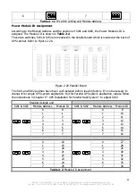
According to the Module Address and the position of SW1 and SW2, the Power Module’s ID is
assigned. The Module ID is shown in Table 2-2.
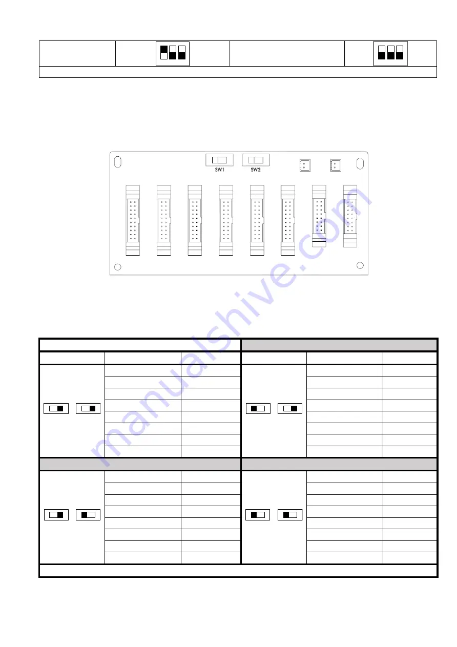
These two switches, SW1 & SW2 are mounted in the Parallel board which is located at the back of
UPS cabinet. Refer to Figure 2-20.
Figure 2-20 Parallel Board
The SW1 and SW2 position have been well installed before leaving factory. It’s not necessary to
change it for single UPS system application. But for Parallel UPS system application, please follow
the instructions in Chapter 9 “ UPS Installation for Parallel Rack System “ to adjust SW2.
Standard single unit
SW1 & SW2
Module Address
Module ID
SW1 & SW2
Module Address Module ID
SW1
SW2
0
0
SW1
SW2
0
9
1
1
1
10
2
2
2
11
3
3
3
12
4
4
4
13
5
5
5
14
6
6
6
15
7
7
7
16
SW1
SW2
0
18
SW1
SW2
0
27
1
19
1
28
2
20
2
29
3
21
3
30
4
22
4
31
5
23
5
32
6
24
6
33
7
25
7
34
Table 2-2 Module ID Assignment


