M2M Control CX320 Technical Manual V1.01
Page 19 of 42
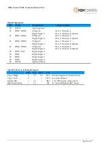
Digital input pins
Pin
Name
Description
Jumper Settings
40
SGND
Signal ground
41
DIN1 / S0IN1
S0 input 1
Digital input 1
Row 1, Position S
Row 1, Position N (
default
)
42
DIN2 / S0IN2
S0 input 2
Digital input 2
Row 2, Position S
Row 2, Position N (
default
)
43
DIN3 / S0IN3
S0 input 3
Digital input 3
Row 3, Position S
Row 3, Position N (
default
)
44
DIN4 / S0IN4
S0 input 4
Digital input 4
Row 4, Position S
Row 4, Position N (
default
)
45
DIN5 / IGN
Digital input 5
46
DIN6
Digital input 6
47
DIN7
Digital input 7
48
DIN8
Digital input 8
49
SGND
Signal Ground
Specification for each digital input:
Min. Typ. Max.
Unit
Logic "High"
8
12
40
VDC Protected against transients and
low-pass filtered
@ 12 VDC input voltage level
In "normal digital input"-mode
Logic "Low"
-5
-
3
VDC
Bandwidth
-
20
-
kHz
Input impedance
-
14
-
kΩ


