background image

M2M Control CX660 Technical Manual V1.02 

Advanced Automotive M2MI/IoT Gateway 


Page 42 of 44 


1.


Remove the frontplate by removing the three screws.  


2.


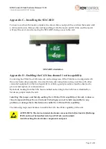
The jumper is located on the bottom side of the circuit board, near the audio jack connector. 


3.


Insert the jumper. 

Please pick a suitable jumper, that is not too long to conflict with the 

endplate.


4.


Place the frontplate, so the connectors fit the openings, then tighten the two screws.


Be careful not to tighten the screws too much, thereby damaging the aluminum.


Appendix E - Open Source Disclaimer 

The M2M CONTROL CX660 products include several open-source software tools. This open-
source software is governed by the terms and conditions of the applicable open source license, and 
you are bound by the terms and conditions of the applicable open source license in connection 
with your use and distribution of the open-source software in this product.  
 

 Jumper 

Summary of Contents for M2M CONTROL CX660

Page 1: ...M2M CONTROL CX660 Advanced Automotive M2M IoT Gateway Technical Manual Version 1 03 ...

Page 2: ...E WLAN Bluetooth Classic Low Energy dual CAN bus Ethernet dual RS232 RS485 and 1 Wire The M2M CONTROL CX660 also sports two USB host port interfaces allowing for the expansion of the device with accessories such as RFID reader additional Ethernet port and additional RS232 RS485 ports The on board I O system can be expanded almost indefinitely and completely transparently by adding Modbus I O modul...

Page 3: ...M2M Control CX660 Technical Manual V1 02 Advanced Automotive M2MI IoT Gateway Page 3 of 44 THIS PAGE IS INTENTIONALLY LEFT BLANK ...

Page 4: ...ble 23 1 Wire bus 23 DC Out 24 Ethernet 24 USB Host interface 24 Audio interface 24 3D movement sensor 26 LED Indicators 27 User LED A and B 27 System LED S1 and S2 28 Switches 29 DIP switch 29 System switch RST 29 Internal Li Ion battery 30 World wide LTE Cat 4 Cellular Engine 31 WLAN and Bluetooth 31 WLAN Technical Data 31 Bluetooth Technical Data 31 99 channels multi GNSS receiver 32 Internal E...

Page 5: ...motive M2MI IoT Gateway Page 5 of 44 Appendix B Installing the internal SIM Card 38 Appendix C Installing the SD CARD 41 Appendix D Enabling the CAN bus channel 1 write capability 41 Appendix E Open Source Disclaimer 42 M2M CONTROL CX660 Specifications 43 ...

Page 6: ...ligence and Infranet Technologies GmbH has failed to eliminate these errors or inaccuracies for this reason This product is a complex and sensitive electronic product Please act carefully and ensure that only qualified personnel will handle and use the device In the event of damage to the device caused by failure to observe the information in this manual and on the device Infranet Technologies Gmb...

Page 7: ... SSL support for all major TCP protocols such as SMTP MQTT and sockets Hardware assisted encryption authentication AES 128 AES 192 AES 256 DES TripleDES HASH RND and RSA signature Wireless Communication Worldwide LTE Cat 4 Multi Band Cellular Engine Dual SIM card readers and support for eSIM Wireless LAN Wi Fi Classic and Low Energy Bluetooth Multi constellation GNSS with GPS GLONASS and GALILEO O...

Page 8: ...o DTMF support for Interactive Voice Response applications Storage Internal flash drive with up to 512 MByte capacity Persistent memory and circular datalogger Standard SD CARD reader USB flash media Power and Battery Operating voltage from 8 to 36VDC Onboard 2 6 Ah Li Ion battery with intelligent charging Encapsulation Exclusive and durable aluminum encapsulation Regulatory Approvals 2007 46 EC U...

Page 9: ...M2M Control CX660 Technical Manual V1 02 Advanced Automotive M2MI IoT Gateway Page 9 of 44 Graphical overview ...

Page 10: ... and USB slave service port The back panel holds all connectors necessary for installation 4 pin X1 power and ignition 6 pin X4 for RS232 and CAN channel 2 12 pin X2 for different communications interfaces 16 pin X3 for analog and digital I O and 6 pin X5 flex inputs A graphical overview of the front and back are shown below Front side view Back side view SIM card reader SD card reader DIP Switch ...

Page 11: ...N SGND 6 3 CAN2 L AGND 3 6 AGND FLXIN3 2 5 FLXIN4 FLXIN1 1 4 FLXIN2 X2 COM1 1 WIRE LED 7 1 1 WIRE SGND 8 2 SGND X3 I O CAN1 L 9 3 CAN1 H AIN2 8 16 AGND SGND 10 4 NC AIN1 7 15 AGND SGND 11 5 RS485 DIN5 IGN 6 14 SGND DC Out 12 6 RS485 DIN3 5 13 DIN4 SGND 4 12 SGND DIN1 3 11 DIN2 DOUT3 2 10 DOUT4 X1 PWR DOUT1 1 9 DOUT2 SUPPLY 3 1 SUPPLY PGND 4 2 DIN5 IGN ...

Page 12: ...on inverting signal 6 RS485 RS485 inverting signal 7 1W LED 1 Wire ID Button LED 8 SGND Signal Ground 9 CAN1 L CAN bus channel 1 L signal 10 SGND Signal Ground 11 SGND Signal Ground 12 DC OUT 5V 500mA DC Out for external equipment Connector X3 16 pin I O connector overview Pin Name Description 1 DOUT1 Digital output 1 2 DOUT3 Digital output 3 3 DIN1 Digital input 1 4 SGND Signal Ground 5 DIN3 Digi...

Page 13: ...ble 5 SGND Signal Ground 6 SGND Signal Ground Connector X5 6 pins FLXIN connector overview Pin Name Description 1 FLXIN1 Flex input 1 2 FLXIN3 Flex input 3 3 AGND Analog Ground 4 FLXIN2 Flex input 2 5 FLXIN4 Flex input 4 6 AGND Analog Ground Connector SER2 RJ45 connector overview fully RS232 compatible Pin Name Description 1 DSR Data Set Ready 2 DCD Data Carrier Detect 3 DTR Data Terminal Ready 4 ...

Page 14: ... Recommended tool Alternative tools Tyco 91501 1 0 20 to 0 50mm2 RS 495 9675 Farnell 1111475 Tyco 91502 1 0 05 to 0 15mm2 RS 495 9675 Farnell 1111476 Extraction tool Tyco 843996 6 extraction tool RS 495 9704 Farnell 1111477 Connector Mini USB B The USB port is for programming and communication with the M2M CONTROL IDE RACP compliant application A standard USB cable with a connector length of 10mm ...

Page 15: ...GND or AGND a wrong polarity on the supply lines will destroy the internal GND connection For the avoidance of such a scenario a fuse can be installed on the positive supply The CX660 also contains an internal high capacity backup battery that will supply the device if the external power supply should fail or be disconnected By default the CX660 is powered down when a power failure occurs This set...

Page 16: ...ed while the CX660 is in low power mode Please consult the M2M CONTROL IDE documentation for additional information When using the function pmExternalPower to disable the external supply it should be observed that any digital outputs that are activated will draw approx 0 6 mA 12VDC from the external power source X3 16 pin I O connector overview Pin Name Description 1 DOUT 1 Digital output 1 9 DOUT...

Page 17: ...logical level applied to this input must be greater than 2 ms to be valid The DIN 5 IGN input is available on both the X1 power connector and the X3 connector together with the other digital inputs only one should be used at a time The power management allows the possibility to configure a wake up on one or more digital inputs with individually configured falling or rising edge detection Please co...

Page 18: ...ent Please be aware that deviations may occur as the system is very noise sensitive Avoid long unshielded wires and large fast changing signals routed parallel to the analog signals The inputs are low pass filtered ESD and transient protected X3 16 pin I O connector overview Pin Name Description 7 AIN 1 Analog input 1 8 AIN 2 Analog input 2 15 AGND Analog Ground 16 AGND Analog Ground Specification...

Page 19: ...uts at specific values making it possible to connect circuits that generate different voltages for different states and then read the state directly An example could be using switches and resistors to create an R2R ladder that allows for connecting multiple switches to a single flex input See the M2M CONTROL IDE documentation for more details about how to configure the flex inputs as digital input...

Page 20: ... IoT Gateway Page 20 of 44 Specification for each flex input Min Typ Max Unit 0 30 VDC Protected against transients and low pass filtered Precision is based on measurements 25 C Resolution 12 Bit Precision 0 4 0 5 FSR Cut off frequency 4 5 kHz Input impedance 120 kΩ ...

Page 21: ...void signal reflections This resistor can be connected by activating the software jumper in the user application Please consult the M2M CONTROL IDE document for the software jumper for a detailed description Be aware that connecting the CX660 to a CAN network can be dangerous If the CX660 is not configured with the correct network parameters it will lead to network corruption and may interfere wit...

Page 22: ...a for serial port 1 RS232 compatible 5 SGND Signal Ground RS232 port 2 The port is a general purpose RS232 port with all control signals according to EIA 561 which defines RS232 on a modular connector The signals are available on the RJ 45 connector located on the top side of the M2M CONTROL CX660 device Connector SER2 RJ 45 connector overview fully RS232 compatible Pin Name Description 1 DSR Data...

Page 23: ... both RS485 ports separately can be activated through the user application in order to terminate the RS485 communication lines with 120Ω By default the RS485 communication lines are not terminated with 120 Ω Please consult the M2M CONTROL IDE documentation for further information on how to use the software jumpers Please note For best performance protection and noise immunity shielded cable advise...

Page 24: ...rs an onboard IEEE 802 3 compatible 100BASE T Ethernet MAC controller and transceiver for communication with peripherals and back end systems over standard Ethernet Please refer to the M2M CONTROL IDE documentation for details on the usage of this interface USB Host interface The M2M CONTROL CX660 offers two high speed USB host ports on the standard USB A connector for connection of various USB de...

Page 25: ... connected internally 3 pin MIC In Pin Name Description Tip MIC_BIAS Bias voltage to the microphone Ring MIC_IN Audio signal from the microphone Sleeve GND Signal ground The specifications on the audio interface connectors are as following Parameter Min Typ Max Unit Description Impedance 4 Ω Output power 2 1 1 4 W W 4 ohm 50pF load 8 ohm 50pF load Headphone impedance 16 Ω AC coupled Full scale inp...

Page 26: ...Y Z with a force as high as 16g in acceleration 2000 dps in rotation and 50 gauss in magnetic field The simplest use is with the power management detecting when the vehicle is moved and the most advanced analytical applications such as driving behavior eco driving Please consult the M2M CONTROL IDE documentation for more detailed information The positions of the 3 axis are as following Specificati...

Page 27: ...wo LED s S1 and S2 are signaling the status and possible errors of the CX660 device User LED A and B LED A and B are composed of four individually controllable LEDs LED named A on the front consists of LED 1 green and LED 2 red LED named B on the front consists of LED 3 green and LED 4 red They are easily accessed from within the application program and it is possible to mix the LED s to obtain a ...

Page 28: ...e it may take some time The progress can also be observed on the display Fast blinking green1 The device has been forced into recovery mode with the use of the system switch The application is not executing 500ms On 500ms Off green1 The device is executing the application program 1 5s On 0 5s Off green1 The device is executing the application program while charging the internal back up battery Fas...

Page 29: ...evice contains a combined reset diagnostic switch This switch is accessible from the front of the unit see graphical overview It is necessary to use a small thin object with a diameter of approx 2 mm for example a straightened out paper clip for this purpose By activating the switch shortly the device will do a complete reset as if the power was removed and reapplied If the reset switch is held do...

Page 30: ...ntenance charge will start every 20 days after the last charge This is to compensate for the battery self discharge etc By default the battery cannot be charged above 45 C or below 0 C The CX660 offers to charge down to 10 C using a specialized algorithm to protect the battery If the temperature is above 45 C the charging will not start and will be postponed until it is below this threshold The te...

Page 31: ...B5 B6 B8 B19 GSM 850 900 1800 1900 MHz SMS Text and PDU UMTS release 7 max 42Mbps down 5 76Mbps upload Cat 6 Digitized audio DTMF capability WLAN and Bluetooth The M2M CONTROL CX660 device contains a combined WLAN Wi Fi and Dual mode Bluetooth radio that shares the same antenna interface WLAN Technical Data 2 4 GHz ISM band IEEE 801 11b g n d e h i WPA WPA2 certification Up to 150 Mbps Bluetooth T...

Page 32: ...ence parameters 148 dBm Time To First Fix2 Autonomous Operation in Standard Sensitivity Mode Reacquisition3 1 sec Hot Start4 1 sec Aided start5 3 sec Warm start6 30 sec Cold start7 35 sec Interface protocol NMEA 0183 v3 01 with GGA VTG GLL GSA GSV and RMC 1 Depends on accuracy of correction data provided by the SBAS service 2 All satellites at 130 dBm 3 Time to get a fix when signal has been block...

Page 33: ...be rejected from the network shortly after Antennas Cellular antenna The M2M CONTROL CX660 device contains an SMA female connector for connecting a suitable antenna When installing the antenna please make sure that the antenna is not in close proximity to metallic parts or anything else that can influence the efficiency of the antenna Please consult the installation guide that follows the antenna ...

Page 34: ...le for example if the SD CARD is often replaced Commercial grade SD CARDs should not be used in applications where a potential failure on the media is considered mission critical For applications that use the SD CARD media extensively and where failure is critical it is recommended to use approved Industrial Grade SD CARDs Infranet Technologies has approved and recommends industrial grade SD CARDs...

Page 35: ...ypical power consumption for the M2M CONTROL CX660 device while it is running Power consumption Device operating in normal mode 12V 24V BAT Device active 85 35 225 mA Device active with Cellular on LTE 110 55 300 mA Cell idle 65 dBm Device active with GPRS on LTE 300 150 700 mA Cell 65 dBm Active communication Battery not charging Device active with GNSS on 100 45 280 mA Mode 4 Device active with ...

Page 36: ...e up source 12V 24V BAT 12V 24V BAT 12V 24V BAT Cellular 20 10 50 mA CAN 1 4 5 2 5 15 mA CAN 2 8 5 4 5 24 mA RS232 1 mode 0 1 4 5 4 2 4 2 2 14 13 mA RS232 2 mode 0 1 5 4 5 2 7 2 5 15 14 mA RS485 4 5 2 5 14 mA Time 1 1 0 7 2 9 0 7 0 4 1 6 0 4 0 3 0 7 mA Din 1 5 1 1 0 7 2 9 0 7 0 4 1 6 0 4 0 3 0 75 mA Power Failure 1 1 0 7 2 9 0 7 0 4 1 6 0 4 0 3 0 75 mA Power Apply 1 1 0 7 2 9 0 7 0 4 1 6 0 4 0 3 0...

Page 37: ...der until a click sound occurs the card will now stay in its position It might be necessary to use a small tool or pencil as the card for protection purposes it is placed underneath the enclosure surface Furthermore a mechanical slide lock can be used to prevent it from being removed accidentally To remove the card slide the lock to its unlocked position and push the card into the reader until a s...

Page 38: ...nged reader with a mechanical lock for secure installation of the SIM card To gain access to the internal card reader the circuit board must be pushed out This operation is described in the following steps 1 Remove the three screws on the backplate 2 Pull gently and slowly the backplate near the GNSS antenna connector The circuit board is fixed inside the encapsulation due to the internal battery ...

Page 39: ... Automotive M2MI IoT Gateway Page 39 of 44 4 The circuit board will not have to be completely removed from the housing The SIM card orientation on the reader is as follows 5 Insert the SIM card in the hinge 6 Close and lock the card reader Lock Unlock ...

Page 40: ... pushed further until the fixing flaps of the battery holder are squeezed inside the battery compartment of the encapsulation 8 Squeeze the first of the two flaps with two fingers on both top and bottom side of the battery holder push into the encapsulation then squeeze the second flap 9 When the baseboard is pushed into the encapsulation align the backplate with the connectors and then secure the...

Page 41: ...tion and may interfere with other connected equipment on the bus Especially in vehicles great precautions must be observed to prevent interruption of communication By default reading from the CAN bus is enabled and writing to the CAN bus is disabled by a hardware jumper inside the unit Installing this jumper and thereby enabling the CAN bus Write capability of the unit is done on the sole responsi...

Page 42: ...e the frontplate so the connectors fit the openings then tighten the two screws Be careful not to tighten the screws too much thereby damaging the aluminum Appendix E Open Source Disclaimer The M2M CONTROL CX660 products include several open source software tools This open source software is governed by the terms and conditions of the applicable open source license and you are bound by the terms a...

Page 43: ...M2M Control CX660 Technical Manual V1 02 Advanced Automotive M2MI IoT Gateway Page 43 of 44 M2M CONTROL CX660 Specifications Technical data are subject to changes ...

Page 44: ...M2M Control CX660 Technical Manual V1 02 Advanced Automotive M2MI IoT Gateway Page 44 of 44 END OF DOCUMENT ...

Reviews: