SMT-BD2
2 - BLOCK DIAGRAM
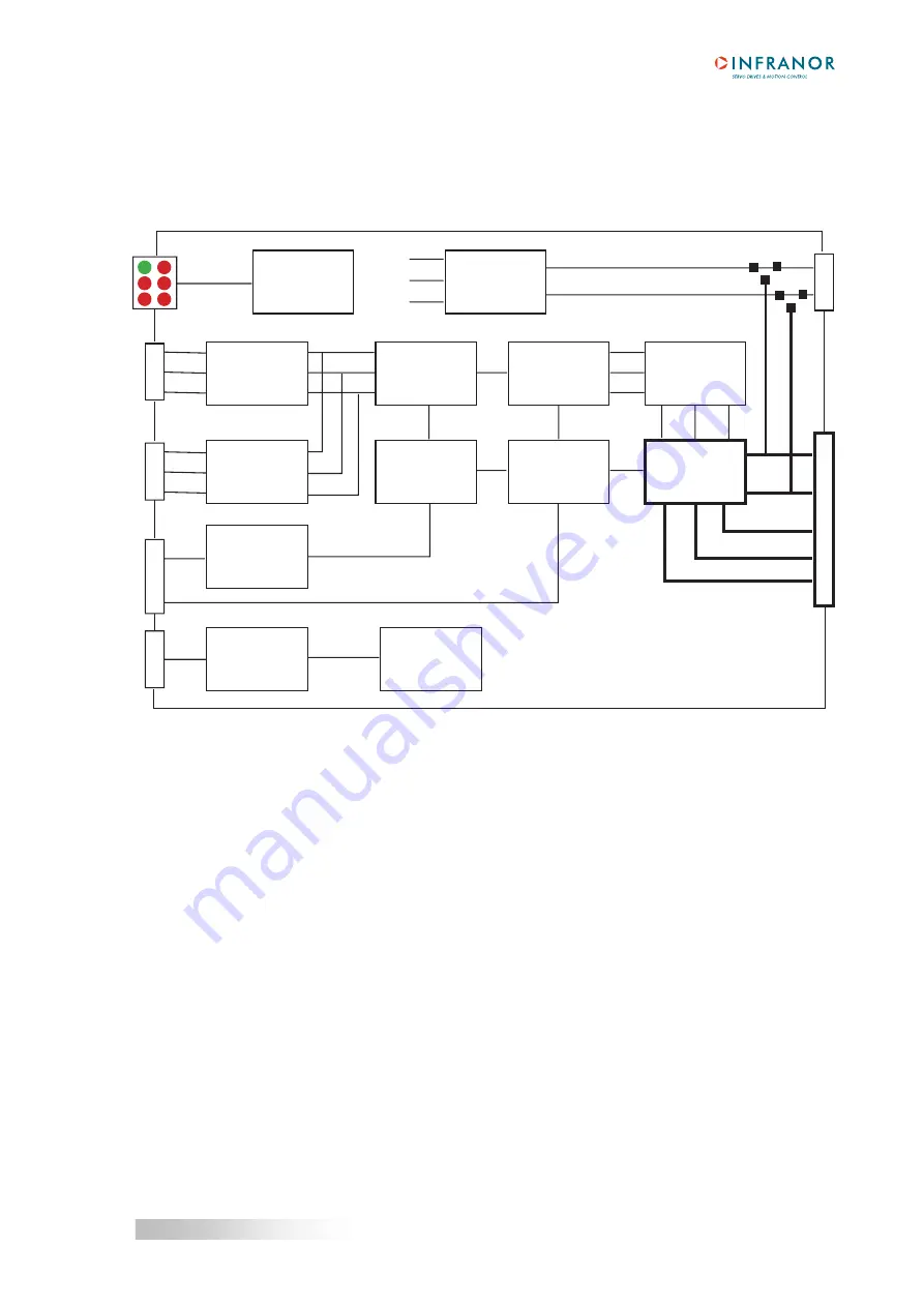
The SMT-BD2 servo module block diagram is presented below.
A
B
Z
A
B
Z
CV
ILIM
X1
X2
X4
X5
+5 V
+15 V
-15 V
U
V
W
PR
10
PR
8
310 V DC
Drive
protections
Encoder
input
Encoder
divider
Speed
ramping
Serial
link
Speed Ref
Speed
Supply
voltages
Position
Pulses
counter
Speed
controller
Drive
parameters
Vector
control
Current Ref
Current
limitation
Current
loops
PWM
power stage
Current Mes
Motor phases
Power
supply
Aux. supply
The PR8 and PR10 connectors are not accessible for direct wiring; they are plugged on the BM20A single-axis
rack or on the multiaxes BF rack according to the SMT-BD2 amplifier housing (
see chapter 3
).
13
Chapter 2 - Specifications


