SMT-BD2
2 - WIRING (according to CEI 801 and EN 55011 standards)
2.1
-
GND
WIRING AND GROUNDING
The reference potential is the
earth (ground)
. Motors and sensors (e HES) are grounded via their
housing. If a potential reference is existing, like a main chassis or a cabinet, with a low impedance between the
various elements, it should be used to connect ALL references to it and also connect this reference to the earth
(ground).
Long reference potential connections are suitable
ONLY
if these connections have an impedance < 0,1
Ω
. Cables
with low potential should
NEVER
run in the proximity of power lines.
Each conductor cable
(carrying a potential)
must be
shielded
. Several wires in the
same sleeve
must be
twisted
and
shielded
.
According to the
CEI 801 standard
, the connectors must be metallic or metal plated and must have
a 360° shield
connection
.
2.2
-
M
OTOR AND SENSORS CABLES
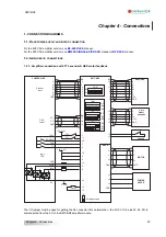
Cable ends should have a metallic collar allowing a 360° shield connection.
Motor cables must be shielded to avoid common mode effects.
Encoder and HES cable must also be shielded.
2.3
-
I
NPUT COMMAND AND SERIAL LINK CABLES
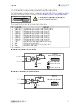
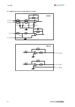
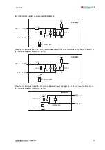
The analog input command signal CV requires a pair twisted and shielded cable. The shield must have a "360°"
connection via metallic collars at both ends. If the shield is connected by means of a pig tail, it must be connected
at one end to a 0 Volt pin of X4 on the amplifier side with a connection as short as possible.
The input command (CV) wiring must be made according to the polarity between the controller and the amplifier
(CV on "diff high" of the controller). The logic 0 Volt is directly connected to the amplifier housing. The connection
continuity is ensured by the fastening screws on the front panels.
The amplifier 0 Volt and the controller 0 Volt
MUST be connected by means of a wire. The shield MUST NEVER be used as a conductor of the 0 Volt
potential
.
The serial link cable must also be shielded according to the above mentioned shielding recommendations.
28
Chapter 4 – Connections


