


User Manual V1.3 | XtracontrolDC2, XtracontrolET2, XtracontrolEC21
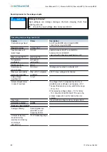
5.2.10 Analogue inputs
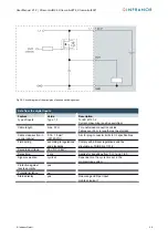
Basic considerations for analogue inputs
An analogue input channel always consists of two connections: AI (U) or AI (U/T) and AGND.
The AI (U/T) channels can measure either voltages (U) or evaluate PT100(0) sensors.
The AI (U) channels can measure voltages or be used for compensation of the line resistances for PT100(0)
measurements (3-wire measurement).
The Earth/Ground/GND lead of a voltage sensor or temperature sensor connected to an analogue input may
be connected only to AGND (not to GND or PE (equipotential)).
Different AGNDs (e.g. on one terminal strip) may not be connected together.
AGNDs may not be connected to the general GND of the control panels or to the “M” on the control unit (GND
and AGND are already connected within the control unit, via a special filter).
AGNDs may not be connected directly to the equipotential bonding conductor (PE) of the machine or system.
Long cables and wires with a small cross-section lead to voltage drops and deviations in PT100(0)
measurements (due to resistance of the lead). These unavoidable deviations must be taken into account
when planning the wiring.
To avoid interference, analogue I/O wires must be kept separate from digital signals and power cables.
Screened cables are advisable for all analogue I/Os. The screen is maintained from the respective sensor or
instrument through into the control panel or close to the control unit.
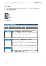
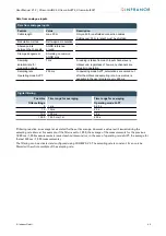
The following counterparts have been tested for the SC-SMT 3.5 (Weidmüller) plug-in connector and are approved
for use with the device:
Weidmüller B2CF 3.50/06/180(F) SN BK
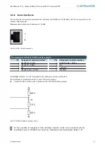
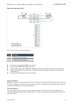
Fig. 29: Analogue inputs X2
Analogue inputs X2
Pin
Assignment
Pin
Assignment
1
AI1 (U/T)
2
AI3 (U/T)
3
AGND
4
AGND
5
AI2 (U)
6
AI4 (U)
44
©
Infranor GmbH
Summary of Contents for Xtracontrol DC2
Page 1: ......


