User Manual V1.1a | XtracontrolEC22
5.3.8
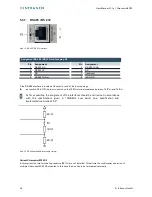
RS 485
Abb. 17: RS 485 interface
Assignment RS 485 interface plug X9
Pin
Assignment
Pin
Assignment
1
NC
5
RS 485 Tx/Rx–
2
NC
6
NC
3
NC
7
(reserved)
4
RS 485 Tx/Rx+
8
ISO GND
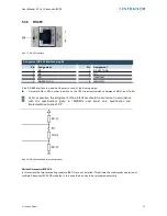
If the RS-485 interface is located at the start or end of the bus topology:
▶
Set switch S4 to ON in order to switch on the 120 terminal resistance between Tx/Rx+ and Tx/Rx–.
Ω
As far as possible, the assignment of the interfaces should be carried out in accordance
with the specifications given in “MODBUS over Serial Line; Specification and
Implementation Guide V1.02”.
Abb. 18: RS-485 switchable terminating resistor
Variant XtracontrolEC22.X2
In this variant the two terminating resistors (681 ) are not installed. This allows the multimaster operation of
Ω
multiple XtracontrolEC22.X2-modules. In this case the bus has to be terminated externally.
© Infranor GmbH
37


