background image

User Manual V1.1a | XtracontrolEC22

Before connecting the power supply, ensure that all cabling is 
correct, including the polarity of all the connections.

2.

Supply power to the device (24 V).

3.

Connect the device to a programming computer using a network cable (X10) and network switch.

4.

Open a web browser on the programming computer.

5.

Enter the IP address of the device into the web browser.

The login screen will appear.

Abb. 23: login window

6.

Use the following user name and password to log into the device:
Name: admin
Password: admin

The web configuration page will be displayed.

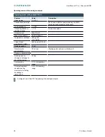
Abb. 24: list of web interface settings

7.

Click on the “Network” link.

The “Network Configuration” page is displayed.

42

©  

Infranor GmbH

Summary of Contents for XtracontrolEC22

Page 1: ......

Page 2: ...er countries EtherCAT is a registered trademark and patented technology licensed from Beckhoff Automation GmbH Germany CiA and CANopen are registered trademarks belonging to CAN in Automation e V ARM and Cortex are registered trademarks belonging to ARM Limited PROFINET is a registered trademark belonging to PROFIBUS Nutzerorganisation e V Modbus is a registered trademark belonging to the Modbus I...

Page 3: ...um Beschreibung 1 0 22 08 2014 First version 1 1 04 07 2016 Corrections new EMC Directive errors data on inputs outputs Additions new variants termination RS485 counter description 1 1a 13 09 2016 Additions harmonisation with other handbooks Infranor GmbH 3 ...

Page 4: ... 5 CONNECTION 15 5 1 Power supply 15 5 2 Earth 17 5 3 Data connections 18 5 3 1 Digital outputs O 19 5 3 2 Digital inputs I 21 5 3 3 Counter inputs 22 5 3 4 Analogue inputs and outputs AIO 24 5 3 5 Example connections of analogue inputs and outputs 31 5 3 6 CAN Bus 35 5 3 7 RS 485 RS 232 36 5 3 8 RS 485 37 5 3 9 Ethernet switch 38 5 3 10 EtherCAT 39 5 3 11 USB 40 6 OPERATION 41 6 1 Switching on an...

Page 5: ... 52 10 1 XtracontrolEC22 52 10 2 Identification plate 55 10 3 Identification 56 11 STANDARDS AND CERTIFICATES 57 11 1 Standards 57 11 2 UL certificate 58 11 3 Declaration of conformity 60 11 4 Notes on copyright and software licences 61 12 CUSTOMER SERVICES ADDRESSES 62 12 1 Customer services 62 12 2 Addresses 62 13 APPENDIX 63 13 1 Table of figures 63 Infranor GmbH 5 ...

Page 6: ...tions Start up Upkeep and maintenance Decommissioning Disposal Always keep this user handbook available alongside the product 1 2 Symbols and visual depictions The following symbols and visual depictions will be used in this handbook Symbol Meaning List entry Individual instruction or list of instructions which can be carried out in any order 1 2 List of instructions which must be carried out in t...

Page 7: ...ty features will result in death or serious injury Take preventive measures WARNUNG Possible serious injury or death Non compliance with the safety features may result in death or serious injury Take preventive measures CAUTION Possible minor injuries Non compliance with the safety features may result in minor injuries Take preventive measures NOTICE Possible damage to property Non compliance with...

Page 8: ...ernational regulations regarding the operating of machinery and facilities where the device is being used must be observed at all times The user must always be kept abreast of any current relevant information regarding the device and its use or operation 1 6 Intended use The XtracontrolEC22 is a modular automation system for industrial control applications within the medium to high performance ran...

Page 9: ...s present wait at least 12 hours before starting to operate the device 1 8 Unpacking Or receipt of the device a check must be made that it is complete and undamaged 1 Check the packaging for external damage 2 If the packaging is seriously damaged or if damage to the contents is evident Do not proceed further with opening the packaging instead immediately inform the transport company and your suppl...

Page 10: ...measures identified If necessary request information from your automation system provider 2 1 Safety instructions The device may be operated only when it is in good working condition Exposed sharp edges pose an injury risk If you discover damage to the front glass of the device do not continue to operate the device Immediately disconnect it from the power supply Working on the device Do not start ...

Page 11: ...ew Abb 1 Overview Item Description Item Description X1 Electrical connection power X13 EtherCAT ETH1 X2 Digital outputs X14 USB 2 0 X3 Digital inputs X15 reserved X4 Analogue inputs and outputs X16 Debug interface X5 Analogue inputs and outputs X20 Functional earth X6 Analogue inputs and outputs S1 Function key Reset and Run Stop X7 CAN Bus CAN0 1 except EC22 51 S2 Terminal resistance CAN Bus ON O...

Page 12: ... or for downloading data directly CAN interfaces except XtracontrolEC22 51 The device has one standard CAN interface which can be used at a speed of up to 1 Mbit s Serial interfaces The XtracontrolEC22 has up to three potential free serial interfaces 2x RS485 1x RS232 Additional interfaces There is also a debugging interface located on the XtracontrolEC22 which can be used in conjunction with a sp...

Page 13: ...rcat via Intel Controller i210 1 USB host interface V2 0 type A 1 CAN interface except XtracontrolEC22 51 3 serial interfaces 1x RS 232 2x RS 485 for communications with other devices and system real time clock 1 µSD card slot USB host 2 0 type A 16 digital inputs max 16 digital outputs max 12 analogue inputs max XtracontrolEC22 20 4 analogue inputs max 6 analogue outputs max XtracontrolEC22 20 2 ...

Page 14: ...free space both above and below the device Abb 2 mounting the device Requirements at least 1 cm free space must be left between the device and the adjacent module 1 Insert the device into the support rail according to the image above so that the plastic snap in hooks between the mounting surface and the rail are pressed in 2 Push the device at the top in towards the mounting surface 3 Push the dev...

Page 15: ... power supply 24 V DC L L1 L2 L3 L4 Supply voltage 24 V DC SELV 15 20 Alternating current proportion Max 5 The direct voltage level must not fall below 20 4 V Energy buffering Power fail 10 ms Internal power supply A power supply for the system electronics for an input voltage of 24 V DC 15 20 is integrated into the device The power supply has integrated protection against reverse polarity and sur...

Page 16: ...pply plug X1 Power supply plug X1 Pin Bez Assignment 1 L external 24 V DC 15 20 power supply internal PLC max 1 A 2 M external GND power supply 3 L1 Digital output DO1 4 supply 24 V DC 20 25 max 2 A2 4 L2 Digital output DO5 8 supply 24 V DC 20 25 max 2 A1 5 L3 Digital output DO9 12 supply 24 V DC 20 25 max 2 A1 6 L4 Digital output DO13 16 supply 24 V DC 20 25 max 2 A1 2Nominal current 2 A at peak ...

Page 17: ...22 Requirements The support rail has a good conductive contact with the control cabinet The control cabinet must be earthed correctly Ensure that the device housing has good conductive contact with the support rail If specifically required in certain installations additional PE conductors may be connected to protect all metallic parts from high voltages on the underside of the device PE connection...

Page 18: ...User Manual V1 1a XtracontrolEC22 5 3 Data connections Abb 4 block diagram 18 Infranor GmbH ...

Page 19: ...ller BCZ 3 81 16 180 F LH Weidmüller BCF 3 81 16 180 F LH Phoenix FK MCP 1 5 16 ST 3 81 LR Abb 5 digital outputs plug X2 Weidmüller SC SMT 3 81 16 180 LF 3 2 Digital outputs plug X2 Pin Bez Assignment 1 2 3 4 O 1 O 2 O 3 O 4 24 V supply from L1 5 6 7 8 O 5 O 6 O 7 O 8 24 V supply from L2 9 10 11 12 O 9 O 10 O 11 O 12 24 V supply from L3 13 14 15 16 O 13 O 14 O 15 O 16 24 V supply from L4 The maxim...

Page 20: ... limited electronically Activation of short circuit protection results in thermal overload and tripping of thermal overload protection Permissible limits based on cold state max 10 000 short circuits overall duration max 500 hours Output delay 0 after 1 typ 1 ms Output delay 1 after 0 typ 1 ms Output capacity 20 nF Rated voltage 24 V DC Voltage drop at rated current 0 1 V Rated current at 1 signal...

Page 21: ... Weidmüller plug in connector and are approved for use with the XtracontrolEC22 Weidmüller BCZ 3 81 16 180 F LH LR Weidmüller BCF 3 81 16 180 F LH LR Phoenix FK MCP 1 5 16 ST 3 81 LR Abb 6 digital inputs plug X3 Weidmüller SC SMT 3 81 16 180 LF 3 2 Digital inputs plug X3 Pin Bez Assignment 1 I 1 C 1 24 V counter input 1 2 I 2 C 2 24 V counter input 2 3 I 3 C 3 24 V counter input 3 4 I 4 C 4 24 V c...

Page 22: ...tively be used as counter inputs C1 C4 Activating this function requires license which can be obtained subsequently The counter inputs C1 C4 have fast filters the unipolar inputs I5 I16 have hysteresis The counter inputs are connected to the signals of the other unipolar inputs There is no changeover switching Available options for the counter inputs up down counter pulse and direction counter qua...

Page 23: ... width at the valid level for at least 1 µs Max frequency signal counter 500 kHz 1 counts s For 100 kHz see specific installation information At the maximum counter frequency the signal transmitter must ensure an edge steepness of at least 20 V µs at the counter input Min pulse width 10 µs Per level Counter resolution 32 Bit Internal pull up 3 kΩ Installation information The counter inputs must be...

Page 24: ...uts plugs X4 X5 and X6 Pin X4 X5 X6 Assignment 1 AI 1 AI 5 AI 9 U T 10 V PT100 1000 2 AI 1 AI 5 AI 9 I 20 mA 3 AGND 4 AI 2 AI 6 AI 10 U 0 10 V 5 AI 2 AI 6 AI 10 I 20 mA 6 AGND 7 AI 3 AI 7 AI 11 U T 10 V PT100 1000 8 AI 3 AI 7 AI 11 I 20 mA 9 AGND 10 AI 4 AI 8 AI 12 U 0 10 V 11 AI 4 AI 8 AI 12 I 20 mA 12 AGND 13 AO 1 AO 3 AO 5 U 0 10 V 14 AO 2 AO 4 AO 6 U 0 10 V Analogue channel wiring Ensure the f...

Page 25: ...ing mode AI PT calculations are carried out after the millisecond sampling rate A new value is available in the user program every 250 ms Digital filtering Possible filter settings Time range for averaging Time range for averaging Operating mode AI PT 10 10 ms 2 5 s 100 100 ms 25 s 1000 1000 ms 1 s 250 s If filtering is active an average is calculated for the set time range However a value is stil...

Page 26: ...ogram 32 bit real floating point number in millivolts mV Maximum permissible permanent overload Max 30 V compared to AGND 30 V max voltage on AI channel Output of digital value in case of overload If a voltage of 10 V is applied to an AI U a plausible value is still given up to approx 15 V The specified accuracy is only valid for the range 10 to 10 V From a voltage of 16 V the values are distorted...

Page 27: ...ce potential AGND Dynamic characteristics Analogue filtering Second grade low pass filter time constant T approx 215 µs Greatest temporary deviation during electrical error testing according to IEC 61131 2 0 5 of measuring range Operating mode temperature inputs AI PT Feature Value Description Connections per input Sensor connection between AI U T and AGND Possible sensors PT100 and PT1000 acc to ...

Page 28: ...puts AI PT Feature Value Description Dynamic characteristics Analogue filtering Second grade low pass filter time constant T approx 500 µs Greatest temporary deviation during electrical error testing according to IEC 61131 2 0 5 of measuring range 28 Infranor GmbH ...

Page 29: ...oads may cause the output to oscillate Load impedance range 1 kΩ Overload protection Short circuit proof Current limitation from approx 22 mA at 25 C ambient temperature Output response during power supply switching on and switching off processes No supply voltage AI I to AGND 40 Ω Low resistance output During device boot up The analogue output is not active during device boot up Deviations from t...

Page 30: ...nt Max 10 mA Max errors at 25 C 0 5 50 mV Temperature coefficient 40 ppm K 0 4 mV K Value of least significant bit LSB 244 ppm 2 44 mV Digital resolution 12 bit Data format in user program 32 bit real floating point number in millivolts mV Dynamic characteristics Build up time for change in full range to 95 of final value 320 µs Overshooting 0 1 of measuring range Greatest temporary deviation duri...

Page 31: ...g AGND for each voltage input Do not connect AGNDs from different channels Only use one channel per function either AI U or AI I Do not connect to the common GND The required connections can already be found on the circuit board Cables to the analogue sensors encoders should be connected as directly as possible avoid the use of terminals and terminal blocks Infranor GmbH 31 ...

Page 32: ...o not connect AGNDs from different channels Only use one channel per function either AI U or AI I Do not connect to the common GND The required connections can already be found on the circuit board Cables to the analogue sensors encoders should be connected as directly as possible avoid the use of terminals and terminal blocks 32 Infranor GmbH ...

Page 33: ...hould be connected as directly as possible avoid the use of terminals and terminal blocks Only connect PT100 0 sensors to AI U T channels Each 14 pin plug in connector has 2 AI U T channels 2 wire measurement Resistance can result in a measurement error which in the case of long cables with a small cross section can be up to 10 If the temperature of the sensor is known this deviation can be subtra...

Page 34: ...verall GND of the device AGNDs which are also used by other input channels should not be connected to the same terminal block in order to avoid changes in the voltage to the AO U and the temperature value Only use the corresponding AGND for each power input Ensure that the cable resistance is substantially lower than the load resistance RL so as to guarantee high measuring accuracy Take into accou...

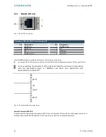
Page 35: ...m baud rate Lowest adjustable baud rate Contacts Assignment Abb 14 CAN interface Assignment CAN interface plug X7 Pin Assignment Pin Assignment 1 CAN_H 5 NC 2 CAN_L 6 NC 3 ISO GND 7 ISO GND 4 NC 8 NC If the CAN interface is located at the start or end of the CAN bus topology set switch S2 to ON in order to switch on the 120 terminal resistance between CAN_L and CAN_H Ω Infranor GmbH 35 ...

Page 36: ... to switch on the 120 terminal resistance between Tx Rx and Tx Rx Ω As far as possible the assignment of the interfaces should be carried out in accordance with the specifications given in MODBUS over Serial Line Specification and Implementation Guide V1 02 Abb 16 RS 485 switchable terminating resistor Variant XtracontrolEC22 X2 In this variant the two terminating resistors 681 are not installed T...

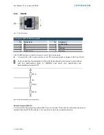
Page 37: ... 120 terminal resistance between Tx Rx and Tx Rx Ω As far as possible the assignment of the interfaces should be carried out in accordance with the specifications given in MODBUS over Serial Line Specification and Implementation Guide V1 02 Abb 18 RS 485 switchable terminating resistor Variant XtracontrolEC22 X2 In this variant the two terminating resistors 681 are not installed This allows the mu...

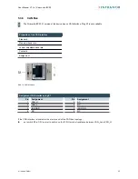
Page 38: ...hernet interface Ethernet interface assignments on plugs X10 X11 and X12 Pin Assignment Pin Assignment 1 TX 5 NC 2 TX 6 RX 3 RX 7 NC 4 NC 8 NC LEDs LED Colour Meaning according to IEEE 802 3 clause 25 SPEED yellow On 100 Mbit s Off 10 Mbit s LNK RCV green Link Data Receive Flashing connection active data transfer underway Off no connection established 38 Infranor GmbH ...

Page 39: ...nsfer in real time Abb 20 EtherCAT interface Assignment of EtherCAT interface plug X13 Pin Assignment Pin Assignment 1 TX 5 NC 2 TX 6 RX 3 RX 7 NC 4 NC 8 NC LEDs LED Colour Meaning according to IEEE 802 3 clause 25 SPEED yellow On 100 Mbit s Off 10 Mbit s LNK RCV green Link Data Receive Flashing connection active data transfer underway Off no connection established Infranor GmbH 39 ...

Page 40: ...he USB stick NOTICE Damage to property and malfunctions due to data loss The USB interface is protected against overloading 0 5 A In the event of a short circuit during operation the control unit may trigger a reset of the system Substantial property damage and damage to the USB device may ensue Before using a USB device check carefully its power requirements NOTICE Failures and malfunctions when ...

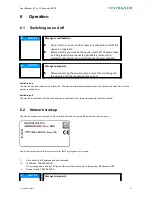
Page 41: ... are correct Switching on The device does not have an on off switch The device starts automatically when the system is switched on or the power is connected Switching off The device is switched off when the system is switched off or the power supply is disconnected 6 2 Network start up The device must be connected to the network with the correct settings before it can be used Abb 22 identification...

Page 42: ...cable X10 and network switch 4 Open a web browser on the programming computer 5 Enter the IP address of the device into the web browser The login screen will appear Abb 23 login window 6 Use the following user name and password to log into the device Name admin Password admin The web configuration page will be displayed Abb 24 list of web interface settings 7 Click on the Network link The Network ...

Page 43: ...on Save 10 Additional settings can also be viewed and or modified on the web configuration page e g system time display resolution TargetVisu 11 In order to activate all of the modified settings reboot the device Remove the device temporarily from the power supply or Click on Reboot in the web interface and then confirm on the next screen by clicking on Reboot Module The device is now configured a...

Page 44: ...operating status LEDs The Run Stop and Error LEDs display the system status Abb 26 location of the LEDs LED Meaning 1 PWR green shows that the power supply to the electronics is correct 2 Run Stop yellow green red shows the system statuses and CODESYS operating statuses 3 Error red shows the device has been stopped due to an error Meaning of the LED displays System statuses are shown using flashin...

Page 45: ...IN_RAM Operating from RAM firmware update active YELLOW flashes 2 x 2 s pause NEEDS_REBOOT Reboot required e g after update RED Error beyond scope of CODESYS runtime system CODESYS operating statuses RED or GREEN PLC_ACTIVE CODESYS runtime system active RED PLC_STOPPED At least one PLC application is stopped PLC_ALL_STOPPED All PLC applications are stopped GREEN PLC_ALL_RUNNING All PLC application...

Page 46: ...between PLC run and stop mode Press and hold Stop PLC with reset of variables except retain data 6 3 3 Real time clock with buffer battery Setting the time The time can be set via the web configuration page or the SysTimeRTC Library CODESYS library Changing the battery The battery is not designed to be changed by the user the manufacturer should be contacted in order to change the battery 46 Infra...

Page 47: ...ched off NOTICE Loss of data MicroSD cards do not have their own write protection system Ensure that no data is deleted or overwritten by accident Inserting a microSD card 1 Turn off the XtracontrolEC22 2 Insert the microSD card into the microSD card slot 3 Turn the XtracontrolEC22 back on The microSD card is now ready for data transfer read write and copy Max possible storage capacity 32 GB Any w...

Page 48: ... 2 Correct the fault 3 Restart the device The device is now ready for use 6 4 2 Unknown IP address If the IP address of the device is unknown maintenance mode can be used to reconfigure it 1 Reboot the device while pressing and holding S1 until the Run Stop LED flashes every 2 seconds The device is now in maintenance mode and can be reached via the default IP address 2 Connect to the device using ...

Page 49: ... touch any connections whilst the device is in operation Before starting any work on the device switch off all power feeds including those to any connected peripherals sensors and programmable devices etc with independent power supplies If the device is used correctly it should not require maintenance Make sure all the ventilation holes are kept free of obstructions Do not open the device If work ...

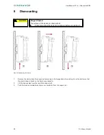
Page 50: ...fore uninstalling it Abb 28 dismounting the device 1 Remove the device from the support rail according to the image above by pushing it in at the bottom so that the plastic snap in hooks on the frame are pressed in 2 Lift the device away from the top of the support rail 3 Push the device downwards and remove completely from the support rail 50 Infranor GmbH ...

Page 51: ...t fee The manufacturer will then deal with the recycling of the device Disposal in accordance with regional regulations Dismantle the device and disassemble it completely into its component parts Send the metal parts for metal recycling Sort the electronic parts circuit boards drives etc Dispose of the electronic scrap in accordance with the national laws and regulations Check that the battery is ...

Page 52: ...hock 15 G approx 150 m s 11 ms duration sinusoidal half wave EN 60068 2 27 test Ea EMC Emitted interference EN 55011 group 1 class B Resistance to interference EN 61131 2 EN 61000 6 2 industrial areas Protection class III Insulation resistance SELV Ue 30 V acc to EN 61131 2 Protection rating IP20 Power supply 24 V power Supply voltage 24 V DC 20 25 SELV max Alternating current proportion 5 Power c...

Page 53: ...cles I O Digital inputs 16 x general purpose input type 1 3 acc to EN 61131 2 Inputs I1 to I4 also as counter inputs C1 to C4 Digital outputs 4x4 0 5 A per output each group with own power supply Analogue inputs A inputs voltage 10 V current 20 mA PT100 1000 2 wire B inputs voltage 10 V current 20 mA Alternatively the adjacent A B inputs can also be used as 1 PT100 1000 3 wire input Analogue outpu...

Page 54: ...n XtracontrolEC22 60 XtracontrolEC22 62 1024 MB onboard 896 for application CAN bus interfaces XtracontrolEC22 00 XtracontrolEC22 20 XtracontrolEC22 50 XtracontrolEC22 60 XtracontrolEC22 62 No type of interfaces Potential isolation Transmission rate Terminal resistance XtracontrolEC22 51 Analogue inputs XtracontrolEC22 00 XtracontrolEC22 50 XtracontrolEC22 51 XtracontrolEC22 60 XtracontrolEC22 62 ...

Page 55: ...ntification plate Item Description Item Description 1 QR code identification no 5 Supply voltage 2 Version delivery version as delivered condition 6 Identification no article no and serial no 3 CE marking 7 Device type description 4 Date of manufacture year calendar week Infranor GmbH 55 ...

Page 56: ...User Manual V1 1a XtracontrolEC22 10 3 Identification The characteristics of the Ethernet controller can be found with the help of the identification key Abb 30 identification key 56 Infranor GmbH ...

Page 57: ...1 Standards and certificates 11 1 Standards Applicable directives EMC directive 2014 30 EC Applicable standards PLC standard EN 61131 2 2008 4 Emission standards EN 61000 6 3 2012 11 Safety provisions DIN EN 61010 2 201 Infranor GmbH 57 ...

Page 58: ...User Manual V1 1a XtracontrolEC22 11 2 UL certificate Abb 31 UL certificate The complete UL certificate can be ordered at Infranor 58 Infranor GmbH ...

Page 59: ... to use the following mark Abb 32 cULus authorisation The devices have been awarded cULus authorisation according to standard UL 61010 2 201 NRAQ 7 Link http database ul com cgi bin XYV cgifind new LISEXT 1FRAME index html UL File Number E242595 Infranor GmbH 59 ...

Page 60: ...User Manual V1 1a XtracontrolEC22 11 3 Declaration of conformity Abb 33 Declaration of conformity The complete Declaration of conformity can be ordered at Infranor 60 Infranor GmbH ...

Page 61: ...are are under the following and further open source licences GNU General Public License GPL GNU Lesser General Public License LGPL Mozilla Public License MPL FreeType License FTL The source code of the free software can be requested at cost by contacting the customer service of Infranor within three years after delivery of the device Infranor GmbH 61 ...

Page 62: ...chland T 49 6181 180 120 F 49 6181 180 1290 e mail support infranor de www infranor de 12 2 Addresses CAN in Automation international manufacturer and user organisation for CAN users in automation CAN in Automation e V CiA Am Weichselgarten 26 91058 Erlangen headquarters can cia de www can cia de EtherCAT Technology Group ETG Headquarters Ostendstraße 196 90482 Nürnberg info ethercat org www ether...

Page 63: ...erature measurement 33 Abb 13 example connection voltage output 34 Abb 14 CAN interface 35 Abb 15 RS 485 RS 232 interface 36 Abb 16 RS 485 switchable terminating resistor 36 Abb 17 RS 485 interface 37 Abb 18 RS 485 switchable terminating resistor 37 Abb 19 Ethernet interface 38 Abb 20 EtherCAT interface 39 Abb 21 USB interface 40 Abb 22 identification plate with device serial number 00001 highligh...

Page 64: ...mparative advantages for its customers in their respective markets The Infranor Brand The Infranor Brand is a synonym for Excellence Cooperation Added value Infranor worldwide Switzerland Germany France Italy Benelux UK Spain USA China Other representations Denmark Poland Slovenia Israel India 09 2016 V1 1a Infranor GmbH Subject to modifications Design Infranor GmbH www infranor com Contact Infran...

Reviews: