31
XtrapulsCD1-a
Chapter 4 - Connections
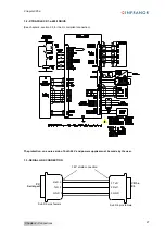
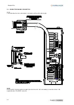
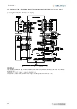
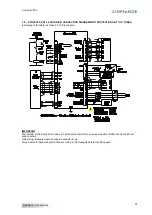
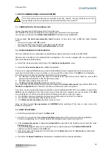
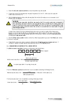
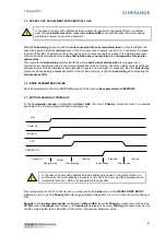
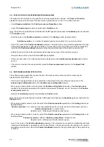
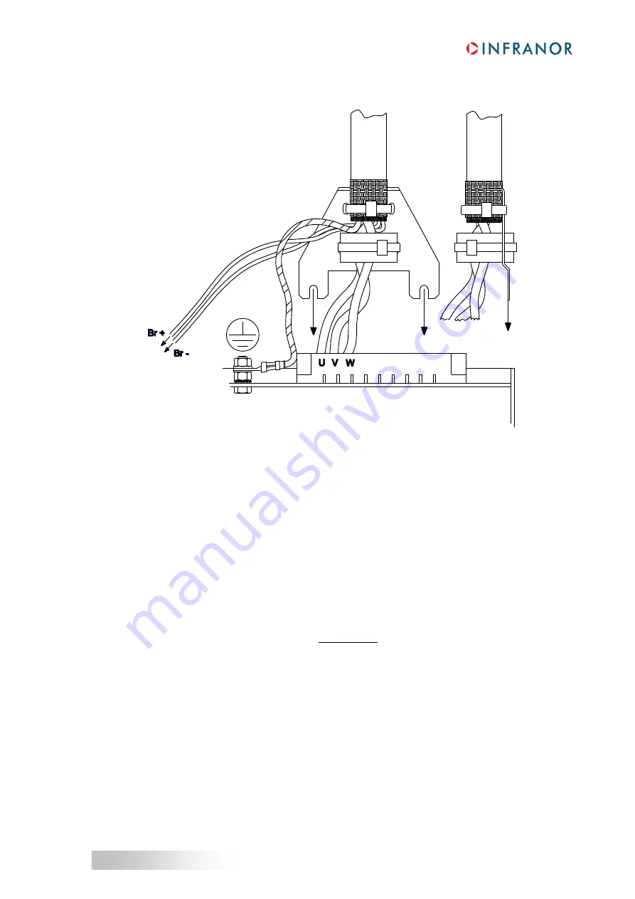
2.3 - CONNECTION VIEW OF XTRAPULS CD1-a-400/30 TO 90 A
Maximum tightening torque of the ground connection: 3.6 Nm.
2.4
– MOTOR, RESOLVER AND ENCODER CABLES
Motors, resolvers and encoders are grounded via their housing.
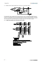
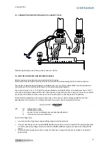
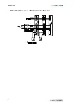
Cable inputs must be made by means of metal connectors with collars allowing the 360° shield connection.
The resolver cable must be pair twisted and shielded (sin, cos, ref.). Motor cables MUST also be shielded and
connected over 360° at both ends as shown on the shield connection diagram.
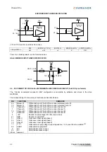
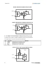
The encoder inputs A, B, C, D, Z and R require pair twisted and shielded cables. The shield must have a "360°"
connection via metallic collars at both ends. If the shield is connected by means of a pig tail, it must be connected
at one end to the GND pin of the connector on the drive side with a connection as short as possible.
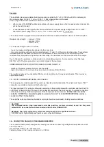
Check that the voltage drop in the power supply lines of the encoder cable is complying with the technical
specifications of the encoder. The voltage drop value for a given cable is calculated as follows:
²]
[
]
[
].
[
.
10
.
40
]
[
6
mm
S
mA
I
m
L
V
U
C
with
U:
voltage drop in volts
Lc:
cable length in meters
I:
encoder current in milliamps (see technical specifications)
S:
cross section in square millimeters
Due to this voltage drop:
an encoder with a large power supply voltage range should be preferred,
if the encoder has got power supply SENSE feedback lines, they can be connected to the power supply lines
in order to reduce the voltage drop by the half (the SENSE feedback signal is not used in the XtrapulsCD1
range),
if none of both solutions above can be used, the user has to supply the encoder by means of an external
power supply.

