TITAN GO Product Manual |
Wiring and Connections
INGENIA | 2022-07-14 08:35:14
72
1.
2.
3.
4.
5.
Adjusting the resolver
7.5.5.1 Resolver Gain
Titan default setting is for a resolver with a transform ratio of 1:0.5
. The transform ratio can be adjusted at
Ingenia facilities.
Please notify the desired resolver specifications when ordering a Titan.
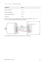
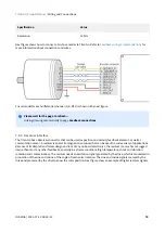
The SIN and COS inputs expect a differential voltage (between positive and negative terminals) of 1.4 V
RMS
or 3.9
V
pk-pk.
However, in some cases it is possible to adjust the gain by adding a resistor in series with the SIN and COS
inputs. This will make a voltage divider with the input differential resistance of 26 k
Ω
. When the gain is correct, the
LOT and DOS LEDs are off.
7.5.5.2 Configuring the resolver
Configure that resolver is the position and or commutation sensor of the driver. Use
for the configuration. Use CANopen or USB for the purpose.
With
motor disabled
check the motor position read by the resolver. Rotate the motor and ensure that
position is well read. Use Ingenia Motion Lab scope with position actual value register being monitored.
If some of the orange or blue LEDs are on this means incorrect resolver gain or alignment. Check the correct
relative position between stator and rotor of the resolver. Use an oscilloscope to detect the amplitude of
sine and cosine (differential) and ensure a
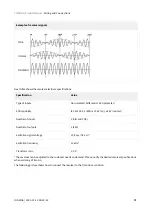
sine wave with desired amplitude is observed (peak 3.9Vp-p of
sine and cosine at their maximum)
. Too much amplitude or too low causes a degradation of read signal
Trick: The gain can be changed by sliding the resolver rotor inwards or outwards relative to the stator. (Z
axis). This changes the reluctance and affects the transform ratio.
Enable the motor in
open loop vector mode, no current loop, no position or velocity loop
. Set frequency
to 1 Hz or lower and start increasing the voltage gently. Use the motion window in motion lab. Observe that
the motor starts moving. Read motor actual current with the scope.
Check that the resolver position is well read. If reading errors appear only when the motor is on, this could
mean some noise being coupled to the resolver and degrading the signal. Wire the resolver as far as possible
from the power cables (to prevent noise coupling). Ensure a good thick and short cable connects the motor
housing and the driver PE (Earth) contact. Connecting the motor housing to PE creates a short impedance
path for coupled noise and therefore is not coupled to the resolver.
Resolvers with independent rotor and stator require fine positioning. Ensure perfect collinearity between
them and follow the resolver manufacturer instructions.
Both resolver LEDs (
LOT
and
DOS
) OFF indicate that the resolver is well positioned and wired.
Summary of Contents for Titan GO
Page 19: ...TITAN GO Product Manual Product Description INGENIA 2022 07 14 08 35 14 19 ...
Page 56: ...TITAN GO Product Manual Wiring and Connections INGENIA 2022 07 14 08 35 14 56 ...
Page 89: ...TITAN GO Product Manual Wiring and Connections INGENIA 2022 07 14 08 35 14 89 ...
Page 101: ...TITAN GO Product Manual Wiring and Connections INGENIA 2022 07 14 08 35 14 101 ...


