TITAN GO Product Manual |
Wiring and Connections
INGENIA | 2022-07-14 08:35:14
98
7.9.1 Fully independent STO channels
The power stage logic is supplied by two cascaded MOSFET transistors. Each transistor is activated by an
independent isolated STO input. The design guarantees that
a single failure will not accidentally activate the
power stage
.
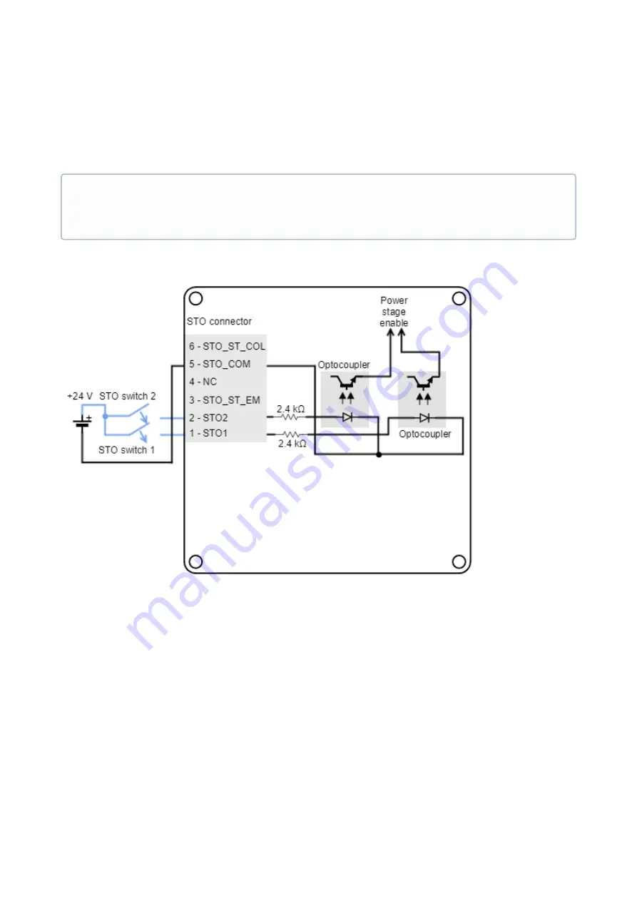
STO inputs have an input voltage of +24 V. Next figure shows how to connect the STO inputs with an external power
supply.
7.9.2 STO status feedback output
The STO also includes a status feedback output. It is automatically controlled by the internal circuits, and the
output is normally active, providing a closed contact.
When one of the STO inputs becomes de-energized (low-
level), the STO_ST becomes low-state
too.
The objective of the STO_ST is to allow external diagnostics of the STO circuit, allowing an increase of the system
reliability. A common-practice in the diagnostics is to delay the stop of the power stage from the deactivation of the
STO_FB and from the deactivation of the STO inputs. This way,
short pulses can be applied for testing the STO
circuit without stopping the system operation
.
The following figure shows the timings corresponding to the STO:
STO firmware notification
An STO stop is notified to the control DSP and creates a
that can be read externally, however its
performance is totally independent from control or firmware. When the STO is not connected it is virtually
impossible to apply power to the drive.
Summary of Contents for Titan GO
Page 19: ...TITAN GO Product Manual Product Description INGENIA 2022 07 14 08 35 14 19 ...
Page 56: ...TITAN GO Product Manual Wiring and Connections INGENIA 2022 07 14 08 35 14 56 ...
Page 89: ...TITAN GO Product Manual Wiring and Connections INGENIA 2022 07 14 08 35 14 89 ...
Page 101: ...TITAN GO Product Manual Wiring and Connections INGENIA 2022 07 14 08 35 14 101 ...


