background image

TRITON CORE Product Manual | 

Product Dimensions and Assembly

INGENIA | 2021-07-07 16:23:18

38

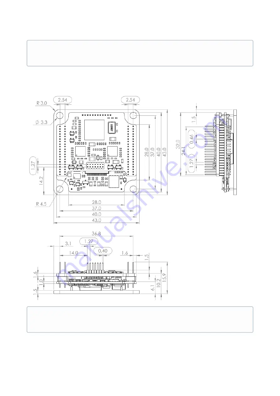
7.2  Triton Core with EtherCAT (TRI-x/48-E-P)

Next figure shows mechanical dimensions in 

mm

. All tolerances are


 ±0.2 mm

.

3D Model

For further detail, download the 

STEP 3D model and PDF 3D

 for the Triton Core TRI-x/xx-C-P. Note that the 

model is simplified: it does not show all the internal components, but does show the major volumes.

3D Model

For further detail, download the 

STEP 3D model and PDF 3D

 for the Triton Core TRI-x/xx-E-P. Note that the 

model is simplified: it does not show all the internal components, but does show the major volumes.

Summary of Contents for TRI-1/48-C-C

Page 1: ...INGENIA CAT S L C Avila 124 2 B 08018 Barcelona TRITON CORE Product Manual Edition 2021 07 07 16 23 18 For the most up to date information visit the online manual...

Page 2: ...eference 14 4 5 3 Output stage 15 4 5 4 System monitoring 16 4 5 5 Protections 17 4 5 6 Inputs 18 4 5 7 Outputs 19 4 5 8 Motion 21 4 6 Equivalent circuits 21 4 7 Architecture 25 5 Pinout 27 6 Signalli...

Page 3: ...8 Application Software 41 8 1 Configuration 41 8 2 Applications 41 8 3 Arduino 41 9 Service 42...

Page 4: ...rejects all liability for errors or omissions in the information or the product or in other documents mentioned in this document The text and graphics included in this document are for the purpose of...

Page 5: ...pment power source wait at least 10 seconds before touching any parts of the controller that are electrically charged or hot 3 3 Precautions The following statements should be considered to avoid seri...

Page 6: ...choice of interfacing methods Its small form factor its capability to operate up to 110 C and the bunch of features that come packed with it makes Triton a valid OEM for critical size applications The...

Page 7: ...4 2 Specifications A list of features of the Triton Core Servo Drive is shown next For further details please check the Operational characteristics section below Electrical and power specifications P...

Page 8: ...99 mA count 9 96 mA count 24 8 mA count Shunt braking transistor Output for external shunt braking transistor activation Cold plate 1 5 mm aluminum sheet 6082 T6 Power connectors Pin headers 1 27 mm p...

Page 9: ...SI over SPI Sinusoidal Trapezoidal Sensors for servo loops Digital Halls Analog Halls Quad Incremental encoder PWM encoder Analog potentiometer Sin Cos encoder Absolute encoder SSI over SPI DC tachome...

Page 10: ...uitry up to 50 mA Protections User configurable DC bus over voltage DC bus under voltage Drive over temperature Drive under temperature Over current Overload I2 t Short circuit protections Phase to DC...

Page 11: ...d CiA 402 compliant EtherCAT Available magnetics are not included Environmental and mechanical specifications Part number TRI x 48 C P TRI x 48 E P Cold plate temperature 40 C to 85 C full current wit...

Page 12: ...onmental and electrical limits of Triton Core Notice this does not represent an operational conditions limit but a limit before permanent damage or destruction References to pin names and pin group na...

Page 13: ...CAN_TTL_x Note 2 5V_D INPUT_x HS_INPUT_x ANALOG_IN_x ENCODER_x OUTPUT_x LED_x BROKEN_WIRE_IN TORQUE_OFF_IN MOTOR_TEMP_IN HALL_x Note 3 GND_P and GND_D are internally connected on a single point Please...

Page 14: ...supply current TRI x 48 C P USB_SUPPLY 5 V Note that the ECAT version cannot be powered by USB only 300 500 m A CBUS Internal DC bus capacitance 16 20 24 F PSTB CAN Standby power consumption TRI x 48...

Page 15: ...se current in DC mode TRI 1 48 y P no heatsink required Limited by ADC range 1 1 ADC I TRA TRI 1 Continuous phase current in Trapezoidal mode TRI 1 48 y P no heatsink required Limited by ADC range 0 6...

Page 16: ...e current in Sinusoidal mode TRI 7 48 y P 5 6 ARMS I PK TRI 1 Peak phase current TRI 1 48 y P Peak time continuous No heatsink required Limited by ADC range 1 1 ADC I PK TRI 4 Peak phase current TRI 4...

Page 17: ...ase current sensing sensitivity TRI 4 48 y P 9 96 mA count I SENSE TRI 7 Phase current sensing sensitivity TRI 7 48 y P 24 8 mA count IERR Phase current sensing tolerance all part numbers 1 2 VMON DC...

Page 18: ...PHY0_x or PHY1_x Air discharge 16 kV Contact discharge 10 kV as per IEC 61000 4 2 Standard Also Power and Logic supplies use unidirectional ESD protections Air and Contact discharge 30 kV Note 2 Power...

Page 19: ...RXDx pins 0 8 V V ANA LO G Analog inputs voltage range ANALOG_IN_x and MOTOR_TEMP_IN 0 3 3 V B ANA LO G Analog inputs resolution ANALOG_IN_x and MOTOR_TEMP_IN 12 bit R TER M Differential encoder termi...

Page 20: ...PHY1_TXDx pins 0 4 V V OH E CAT_L ED High level voltage on LED_ECAT_LINKx pins IECAT_LED 50 A 3 2 V V OL EC AT_LE D Low level voltage on LED_ECAT_LINKx pins IECAT_LED 50 A 0 1 V I ECAT_ LED LED_ECAT_L...

Page 21: ...fTORQUE Torque loop refresh frequency 1 0 kHz fSERVO Position velocity loops refresh frequency 1 kHz fERR Frequency tolerance Over operating temperature range 150 ppm DMAX Maximum DC Bus utilisation...

Page 22: ...21 07 07 16 23 18 22 Analog inputs ANALOG_I N_x 8 kHz 10 ksps Absolute encoder SPI chip select ABS_EN CODER_C S Digital hall inputs 1 HALL_x 159 kHz 10 ksps Analog hall inputs 1 HALL_x 10 kHz 10 ksps...

Page 23: ...coder broken wire protection input BROKEN _WIRE_IN 1 ksps Analog and digital encoder inputs 3 ENCODER _x 6 MHz Firmware glitch filter up to 30 MHz 10 ksps Equivalent circuit Function Associate d pins...

Page 24: ...SPI interface ABS_ENC ODER_SDI ABS_ENC ODER_SD O ABS_ENC ODER_SC K 2 Mbps SSI encoder max 1 kHz USB interface Includes ESD protections USB_DAT A USB_DAT A 12 Mbps Equivalent circuit Function Associate...

Page 25: ...sing a PTC thermistor of a higher nominal resistance Contact Ingenia Support for more info Note 3 Analog and Digital encoder share the same input pins In any case differential encoders use both positi...

Page 26: ...TRITON CORE Product Manual Product Description INGENIA 2021 07 07 16 23 18 26...

Page 27: ...input Logic circuits supply positive can be directly tied to V_BUS pins 2 3 4 V_BUS Power Power supply positive Check Product Description section for more detail 5 6 7 8 GND_P Power Power supply nega...

Page 28: ...nput Analog input for a motor temperature sensor PTC thermistor kind is preferred 30 HALL_1 Input Digital Halls Digital Analog hall 1 sensor input 31 HALL_2 Input Digital Analog hall 2 sensor input 32...

Page 29: ...Digital output 5 43 OUTPUT_4 Output Digital output 4 44 OUTPUT_3 Output Digital output 3 45 GND_D Power I Os supply Reference 0 V for external circuitry 46 5V_D Power 5 V supply for external circuitr...

Page 30: ...ect output terminal 62 GND_D Power Reference 0 V for external circuitry 63 ABS_ENCODER_S DO Output Absolute encoder SPI Serial Data Output stream terminal 64 ABS_ENCODER_ SCK Output Absolute encoder S...

Page 31: ...s pin 75 USB_DATA Bidirectional Negative terminal for USB data stream 76 TORQUE_OFF_I N Input STO Digital input to disable the power stage of the drive 77 GND_D Power USB Reference 0 V for external ci...

Page 32: ...for the Transmitter of the EtherCAT Port 1 89 GND_D Power Reference 0 V for external circuitry 90 GND_D Power Reference 0 V for external circuitry 91 PHY0_TXD Output Positive terminal for the Transmit...

Page 33: ...power MOSFET that switches a shunt braking power resistor and also a SHUNT LED Next table shows the meaning of each signal LED signal Meaning 3 3V_D The internal logic power supply is working LED_FAU...

Page 34: ...sh Sync error The sync message has not been received within the configured communication cycle period time out On Bus off The CAN controller is bus off RUN LED indicates the status of the CANopen netw...

Page 35: ...nformation regarding communication status according to EtherCAT specification LED_ECAT_RUN and LED_ECAT_ERROR signals used for CAN operation in the Triton Core part number TRI x 48 C P are intended to...

Page 36: ...d to drive YELLOW Link 0 and Link 1 LEDs typically integrated in the RJ45 connector housing to indicate the state of the physical link activity on each port Signalling fits the following states table...

Page 37: ...ber All Triton variants are provided with 4 x 3 3 mm holes in a 37 mm x 37 mm square for M3 screws mounting 7 1 Triton Core with CAN TRI x 48 C P Next figure shows mechanical dimensions in mm All tole...

Page 38: ...l For further detail download the STEP 3D model and PDF 3D for the Triton Core TRI x xx C P Note that the model is simplified it does not show all the internal components but does show the major volum...

Page 39: ...rface is essential to achieve desired performance Due to the dimensions of the plate it is essential that the thermal pad is soft enough to compensate the flexing during assembly Next are some thermal...

Page 40: ...he pressure is only applied near the screws and air bubbles are formed decreasing the heat transfer dramatically Manufacturer Part Number and description Thickness before compression Thermal conductiv...

Page 41: ...your own application to communicate with the Triton and develop standalone or multiaxis systems you can use the multi platform library MCLIB 8 3 Arduino To start an Arduino based project easily conne...

Page 42: ...RCELONA SPAIN 9 Service We are committed to quality customer service In order to serve in the most effective way please open a ticket on our service desk at www ingeniamc com support or contact your l...

Reviews: