Triton Go Product Manual |
Connectors Guide
INGENIA | 05/29/2017
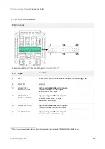
36
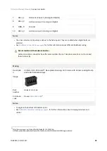
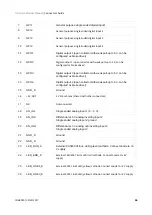
7
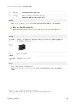
GPI1
General purpose single ended digital input 1
8
GPI2
General purpose single ended digital input 2
9
GPI3
General purpose single ended digital input 3
10
GPI4
General purpose single ended digital input 4
11
GPO1
Digital output 1 (open collector with weak pull-up to 5 V, can be
configured as brake driver)
12
GPO2
Digital output 2 (open collector with weak pull-up to 5 V, can be
configured as brake driver)
13
GPO3
Digital output 3 (open collector with weak pull-up to 5 V, can be
configured as brake driver)
14
GPO4
Digital output 4 (open collector with weak pull-up to 5 V, can be
configured as brake driver)
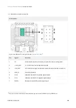
15
GND_D
Ground
16
+5V_OUT
5 V 200 mA max (shared with other connectors)
17
NC
Not connected.
18
AN_IN1
Single ended analog input 1 (0 ~ 5 V).
19
AN_IN2-
Differential ±10 V analog inverting input 2
Single ended analog input 2 ground
20
Differential ±10 V analog non inverting input 2
Single ended analog input 2
21
GND_D
Ground
22
GND_D
Ground
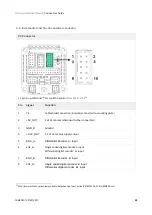
23
LED_RUN_K
External CAN/ECAT Eun LED (green) cathode. Connect anode to +5
V supply
24
LED_ERR_K
External CAN/ECAT Error LED (red) cathode. Connect anode to +5 V
supply
25
LED_LINK1_K
External ECAT Link1 LED (yellow) cathode. Connect anode to +5 V supply
26
LED_LINK0_K
External ECAT Link0 LED (yellow) cathode. Connect anode to +5 V supply


