Triton Go Product Manual |
Wiring and Connections
INGENIA | 05/29/2017
62
62
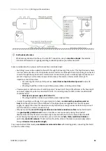
http://www.wagocatalog.com/okv3/index.asp?lid=5&cid=51&strBestNrID=2160206
63
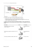
http://www.wagocatalog.com/okv3/index.asp?lid=5&cid=51&strBestNrID=2160224
7.3.3 Motor wiring recommendations
Wire section
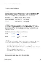
The minimum wire section is determined by the motor current. It is preferred to use
wide section stranded
wires
to reduce impedance, power losses and ease the assembly. Insulator size should not exceed 5 mm
(connector pitch). Following table indicates recommended section for the Triton Go Servo Drive:
Connection
Minimum wire size
Maximum wire size
Stranded wire (preferred)
0.5 mm
2
(20 AWG)
1.5 mm
2
(16 AWG)
Solid wire
0.5 mm
2
(20 AWG)
1.5 mm
2
(16 AWG)
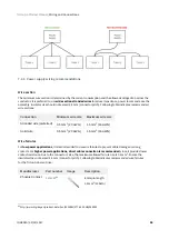
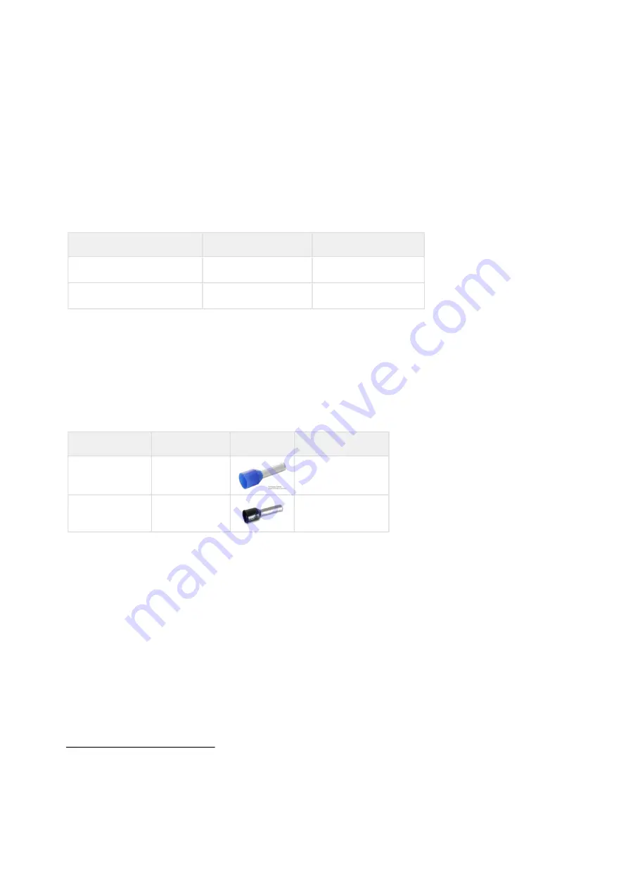
Wire ferrules
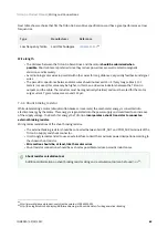
For
low power applications
, it is recommended to use wire ferrules to prevent cable damage or wrong
contacts. For
higher power applications, direct cable connection is recommended
, since it provides lower
contact resistance. Due to the connector's size, the maximum allowed ferrule size is 0.5 mm
2
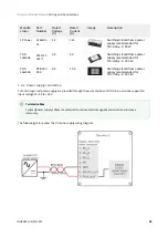
. Ensure the
insulator does not exceed 3.5 mm (connector pitch). Following table indicates recommended wire ferrules
for the Triton Go Servo Drive:
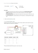
Manufacturer
Part number
Image
Description
WAGO
0.5 mm
2
(20 AWG)
WAGO
1.5 mm
2
(16 AWG)
Motor choke
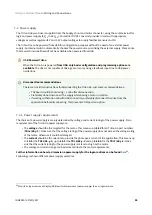
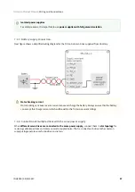
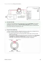
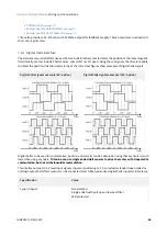
In applications where electromagnetic compatibility is a concern or that must comply with the EMC standards,
the use of an external common mode choke is necessary. Some choke wiring recommendations are:
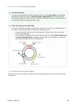
• Place the choke as close to the drive as possible.
• Make sure the chosen choke
does not saturate at the maximum operating phase current
. If this
happens, the choke temperature would increase rapidly.
•
Only 2 or 3 turns of the motor cables
to the choke are recommended for best performance. Doing more
than 3 turns reduces choke effectiveness, as capacitive coupling between wires would bypass the choke
effect.
•
PE conductor should NOT
pass through the choke.
• Avoid contact of the toroid core with a grounding point.

