Triton Go Product Manual |
Wiring and Connections
INGENIA | 05/29/2017
70
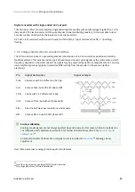
The Triton Go Servo Drive has one differential digital encoder interface, with optional index signal input. Index
(Z) is a single pulse per revolution signal that indicates an absolute position. Next table lists digital encoder
inputs main features.
Specification
Value
Type of inputs
Non-isolated. Differential or single ended. ESD protected
Number of inputs
3 (A, B and Index)
ESD capability
IEC 61000-4-2 (ESD) ± 30 kV (air), ± 30 kV (contact)
Nominal voltage range
0 ~ 5 V
Maximum voltage range
-0.5 ~ 5.5 V
Maximum recommended working
frequency
10 MHz (differential)
1st order filter cutting frequency (-3
dB)
6 MHz
Maximum readable pulse frequency
30 MHz
Termination resistor
220 Ω (between ENC_x+ and ENC_x-)
Bias resistors
ENC_x+ (positive input) 1 k
Ω
to 5 V
ENC_x- (negative input) 1 k
Ω
to 2.5 V (equivalent)
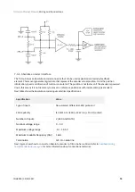
For encoder signal reception, an analog differential line receiver with an hysteresis comparator is used. The high
signals (ENC_A+, ENC_B+ and ENC_Z+) are pulled up to +5 V, and the low signals (ENC_A-, ENC_B- and ENC_Z-)
are biased to 2.5 V. This arrangement let the user to connect either differential output encoders or single ended
encoders (both open collector and totem pole).
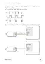
The encoder interface also accepts an RS-422 differential quadrature line driver signal in the range of 0 V to 5 V,
up to 10 MHz. When single ended encoder is connected, only high signals (ENC_A+, ENC_B+ and ENC_Z+) must
be used.
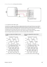
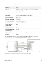
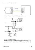
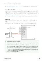
Next figures illustrate how to connect a differential and a single ended encoder to the Triton Go Servo
Feedback wiring recommendations
for more information about connections and
wires.
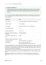
High precision applications
High resolution motor mounted encoders allows excellent velocity and position control at all speeds.
Encoder feedback should be used for applications requiring precise and accurate velocity and position
control. Digital encoders are especially useful in applications where low-speed smoothness is the
objective.

